
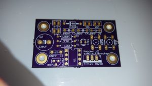
 Component Side
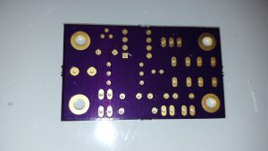 Solder Side
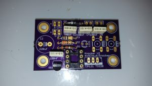
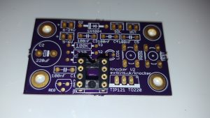 Start by inserting the 8 pin IC holder, ensure that the cut out at one end matched the cut out on the board silk screen. Carefully solder the pins on the solder side of the board, being careful not to bridge the pins with solder.
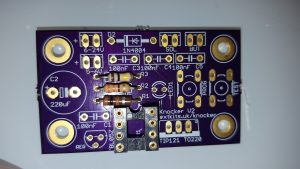 Select the three resistors 100K(brown black yellow),330R(brown black brown) and 100R (brown black brown)
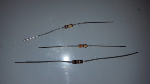 Insert the resistors into the three resistor places shown and solder.
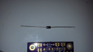 Insert the diode into its place on the board. Ensure the end of the diode with the white line matches the identification on the board
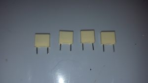 Insert the 4 capacitors in the position shown
On V4 boards the regulator indent is incorrect, on these boards only, the flat side of the regulator needs to go to the curved side of the silk screen on the PCB.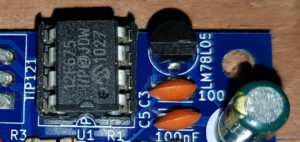
Insert the regulator, Ensure that the D shape of the regulator, matches the D around the silk screen. If you are running on batteries you may want to leave out the regulator look at the use guide for more details
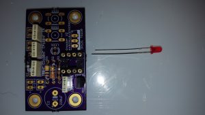 Insert the LED match the Flat of the LED with the Flat on the circuit board. and solder in place
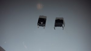
 Insert the two push buttons and solder in.
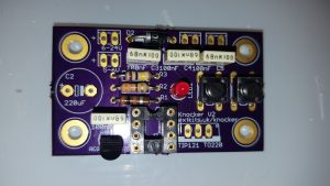
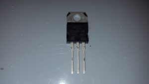 Insert the transistor in to the holes shown
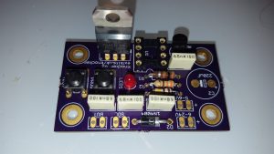 Ensure that the tab is the same way around as shown on the PCB
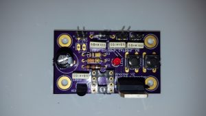 Insert the capacitor checke that the -ve leg designated by the —– on the side of the can
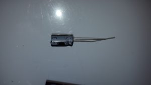 Matches the -ve on the capacitor ident on the PCB
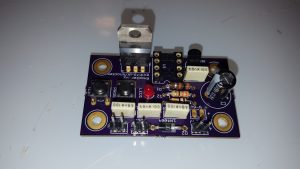 Add the two pin headers into the solenoid button and power connectors. Leave the header out of the 5-6V position unless you are using the alternative supply arrangement detailed in the use guide
Your board is done, enjoy…
