
Take the PCB and ensure it is clean and dry
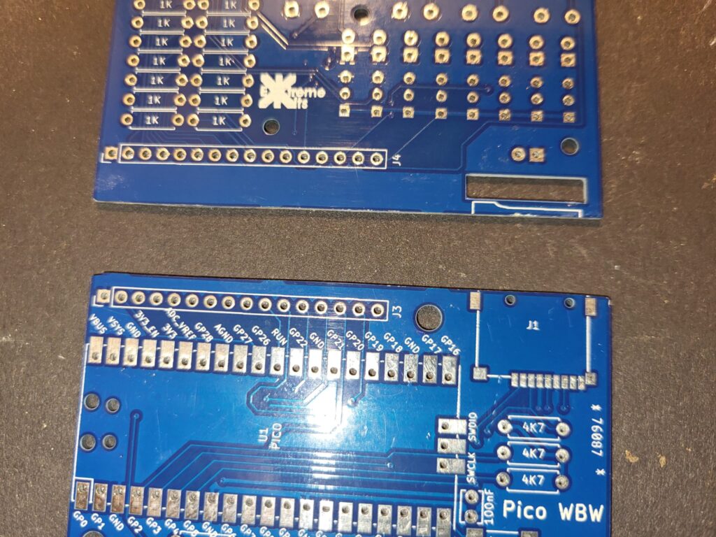
Break the PCB’s into two pieces and file down the “mouse bites”

Solder in the surface mount components. Ensure the sounder (+) matches the + on the ident of the PCB.
Ensure the PICO is flat to the PCB and aligned accurately. Do not use headers, solder directly to the PCB.
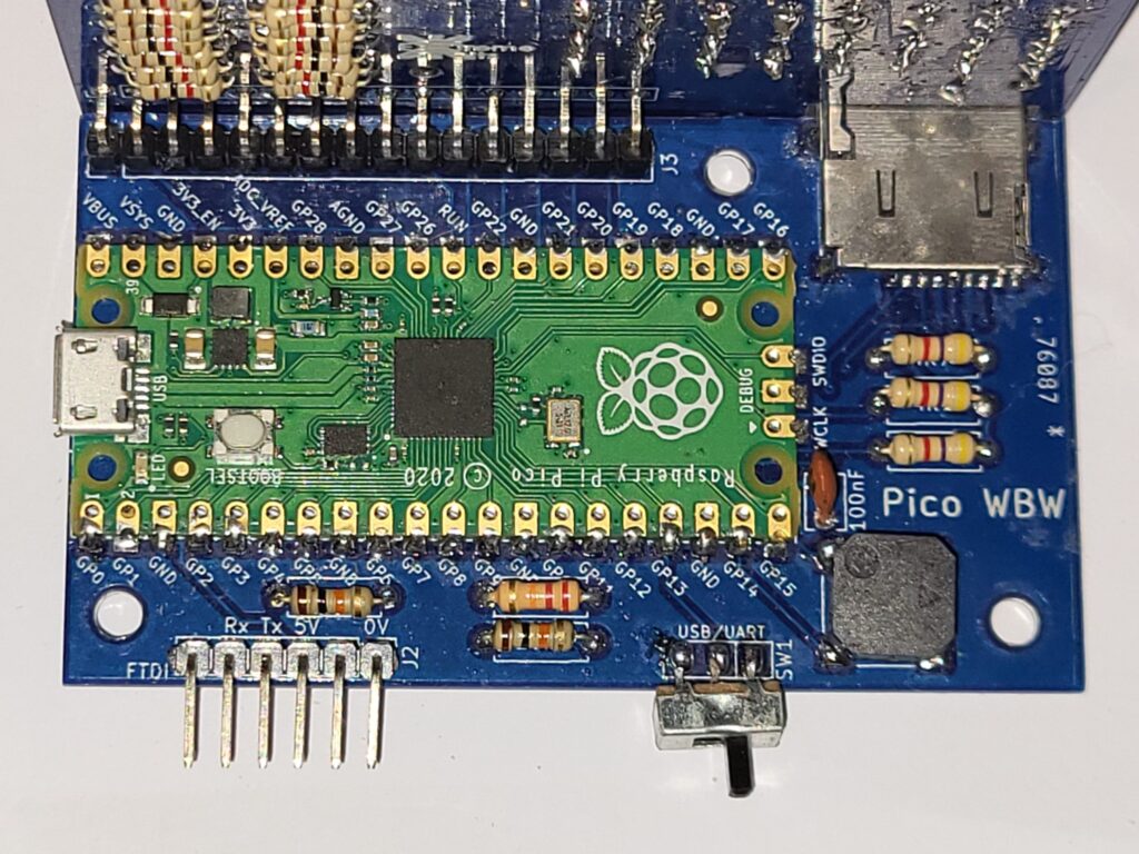
Insert the resistors 3 x
4k7resistors, the 2 x
10kresistors and the
22kResistor
Also the small brown 100nF Capacitor
Solder in the 6 way 90 degree header and the 16 way 90 degree connector and the switch.
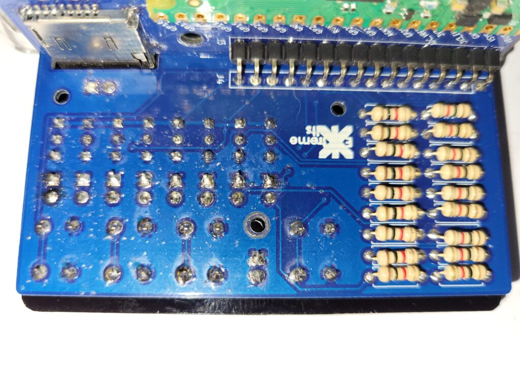
On the rear of the Front panel, Solder in the 18 x
1kResistors
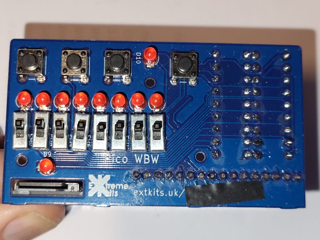
On the front of the front panel, Solder in the 10 leds, ensure that the short leg (cathode) goes to the square pad on the PCB.
Solder in the 4 buttons and 8 switches, ensuring they are all flush to the PCB.
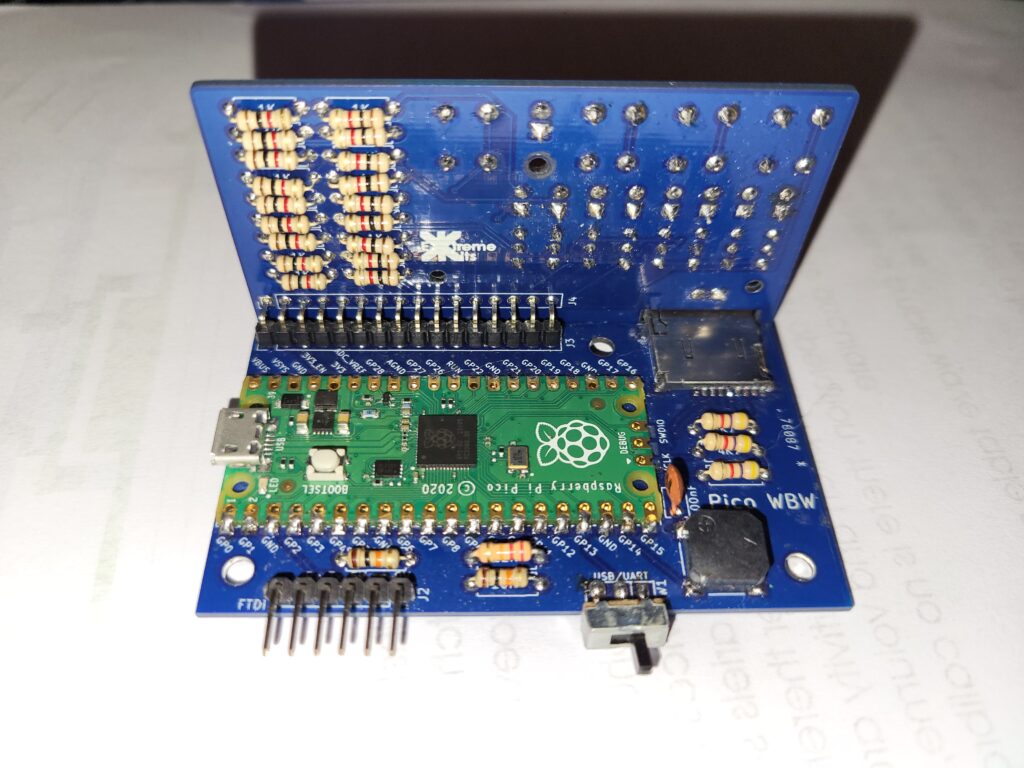
Place the two PCBs up flush to each other along the 16 way 90 degree connector. So the two PCBs are at 90 degrees to each other.
Trim off the excess pins where they come through the front of the PCB .
