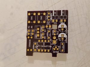
 The unpopulated PCB component side up.
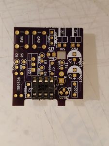 Solder in the IC socket, ensure the cut-out in the IC holder matches the cut-out on the ident on the PCB
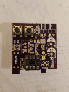 insert the two buttons and solder in place
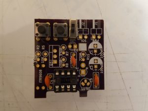 Insert and solder in the switch and the three capacitors
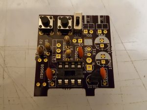 Insert and solder the 5 resistors and the regulator.
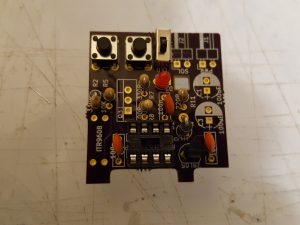 add the LED the flat on the side of the LED needs to go to the square pad on the PCB and the diode, ensuring that the white band on the diode points to the square pad on the PCB
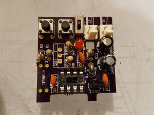 Solder in the two capacitors, match the white stripe on the capacitors for the white D on the PCB ident
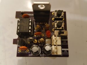 Solder in the transistor
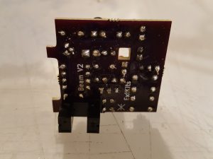 Finally flip the board over and solder the slotted opto on to the reverse of the board ensuring it is flush to the PCB.