
Tools required
Posidriv Screwdriver – medium (suitable for M3-M5 screws)
Posidriv Screwdriver – small (suitable for M2-M3 screws)
Fine nosed plyers
Side Cutters
Small hammer
Needle files (not essential, but useful)
Small Magnet or Bluetak (not essential, but useful)
Building the Acrylic frame and crank
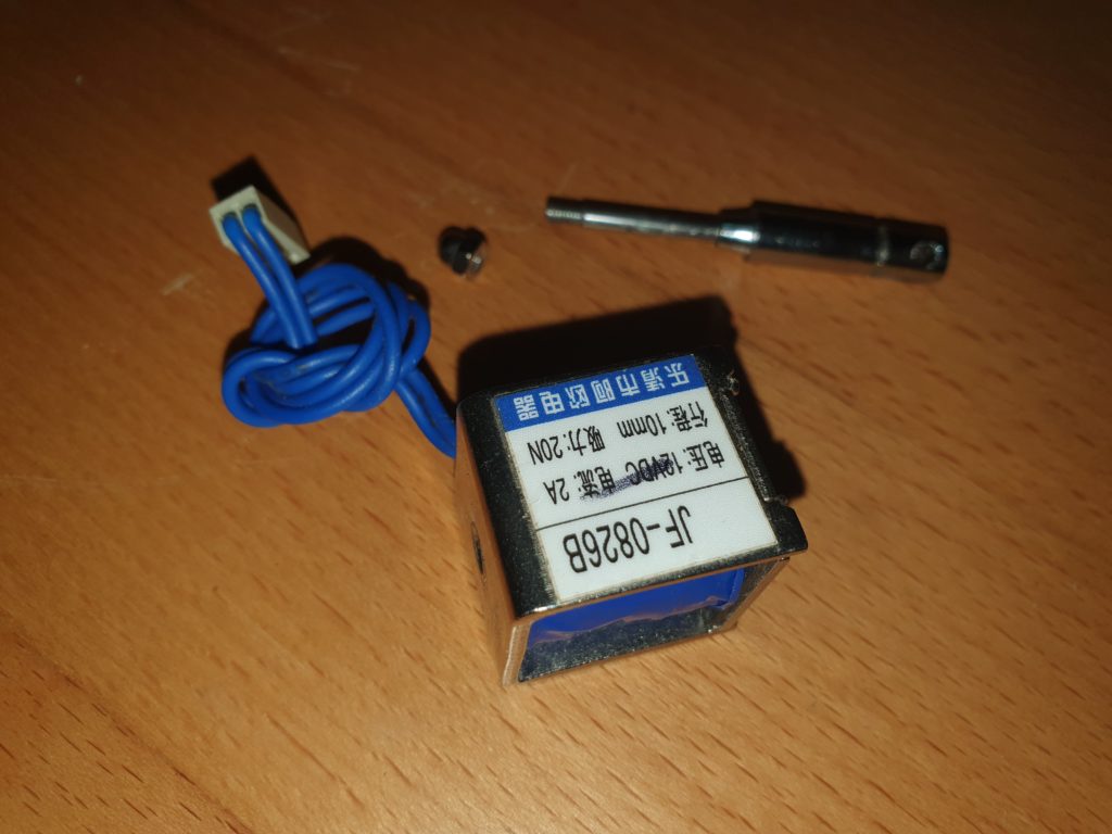
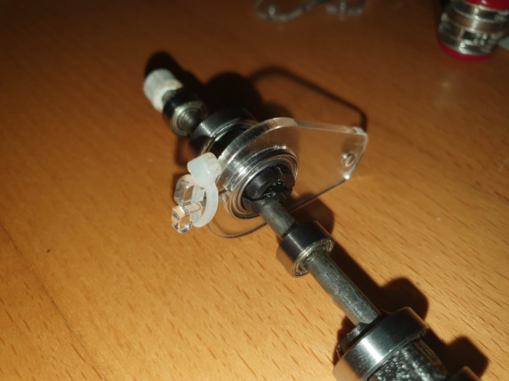
With each of the solenoids, remove the spring , circlip and unscrew the dome nut from the end of the solenoid armature.
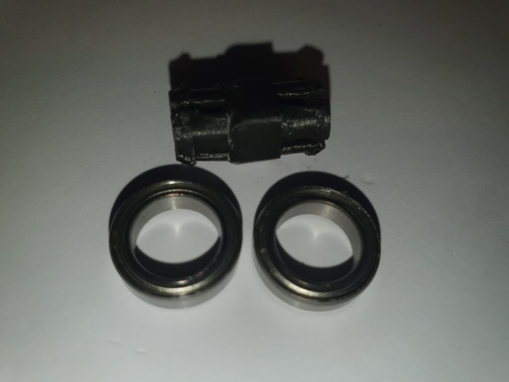
Take two of the 15mm bearings and push them onto the bearing holder.
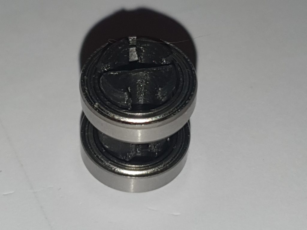
Do this for both bearing holders (all 4 on the V8 engine)

Push the axel though the round (offset) hole in the bearing holders. Use a coin to assist.
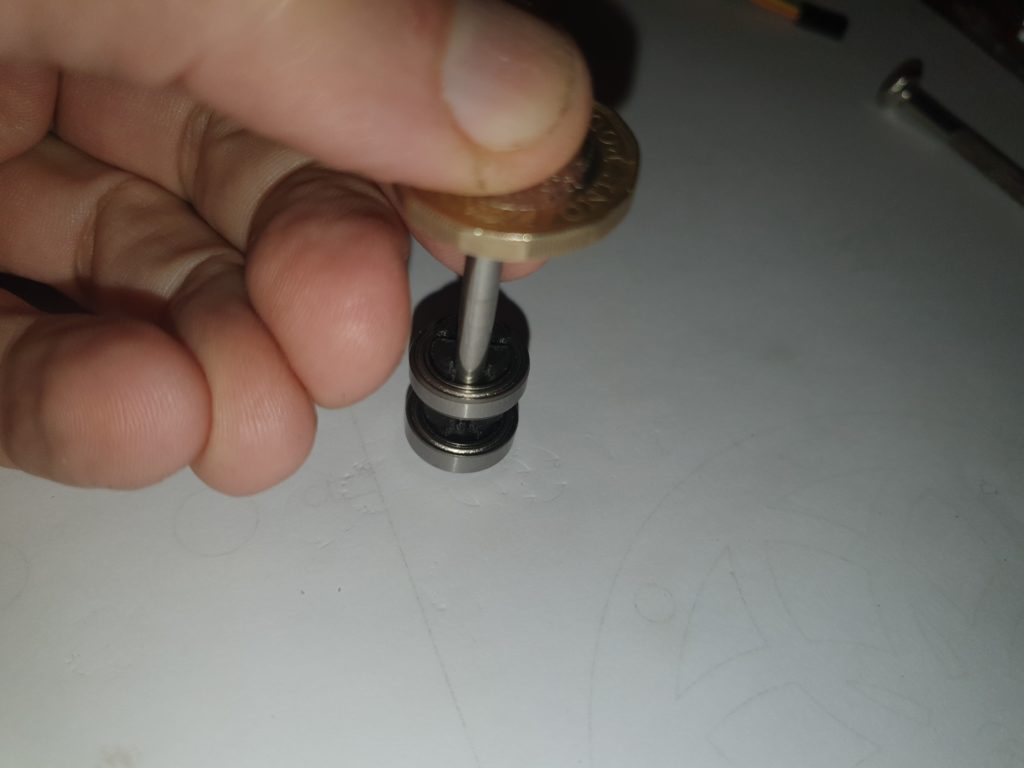
Be careful to push the axel in straight. Brace the other end against an edge, and then against a table edge when the axel comes through the other end.
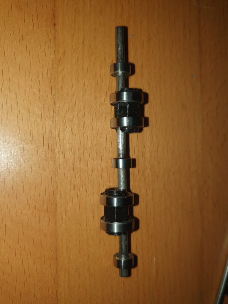
alternate the 10mm bearings and bearing holders down the axel.
Refer to this guide for the V4
and this guide for the V8
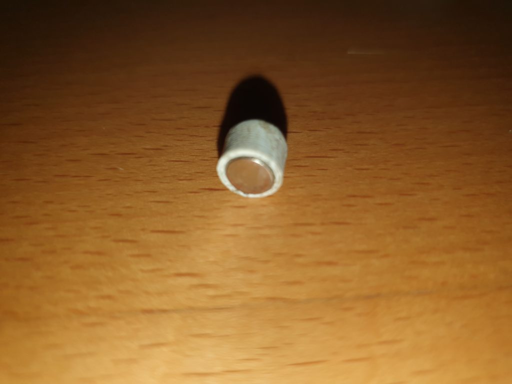
Please Read regarding the diamagnetic magnet and holder
Push on the magnet holder onto the end of the axle indicated by the position guide above.
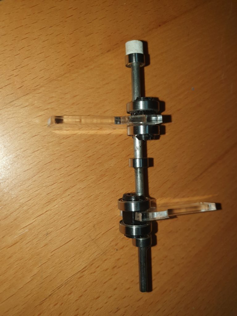
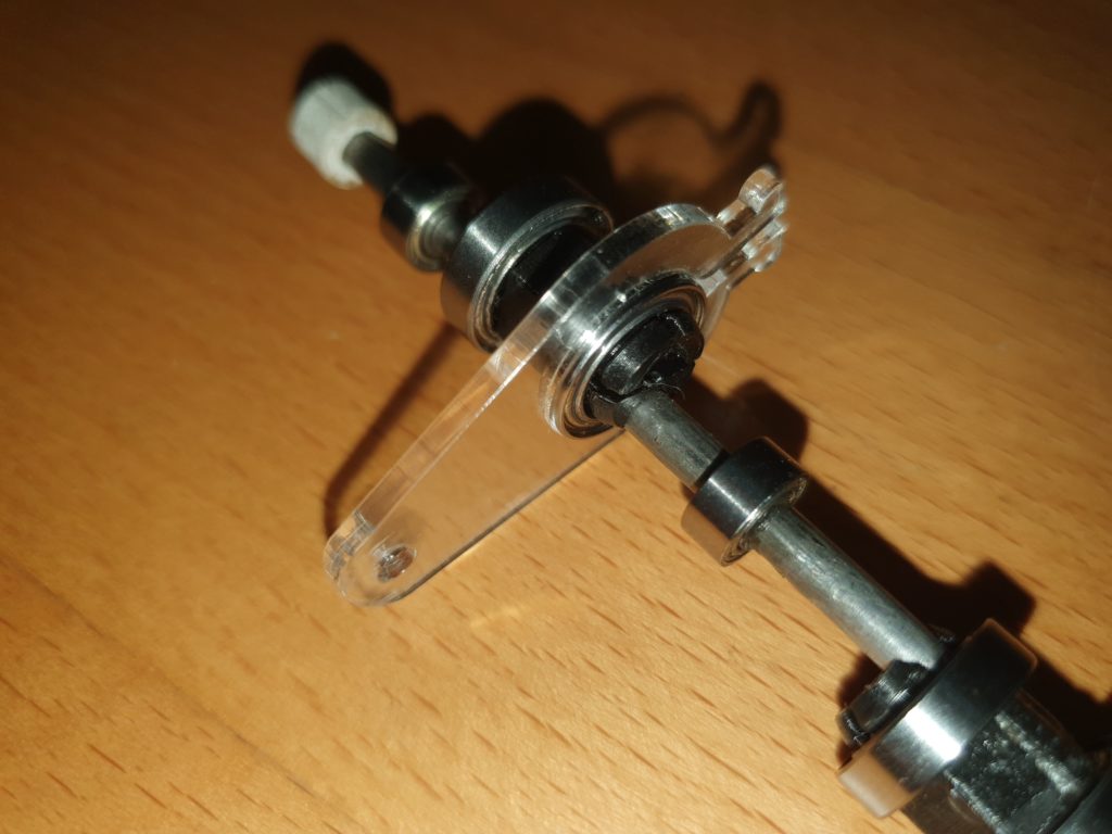
V4: Using the two acrylic spanners set the two bearing holders 180 degrees apart (as shown) referring to the shaft setup.
V8: Using two acrylic spanners set the 4 bearing holders in 45 degree increments referring to the shaft setup.
Refer to this guide for the V4
and this guide for the V8
On each of the 15mm bearings push on the conrod.
When all of the conrods are in place, secure with a 2mmx100mm cable tie, and trim off the end.
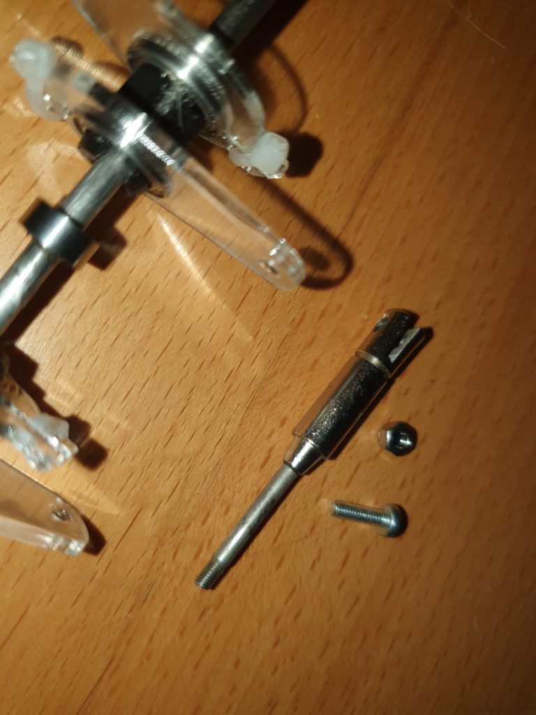
Take the Armatures that you removed from the Solenoids and attach them to the con-rods with m3 x 12mm bolts and m3 nylock nuts
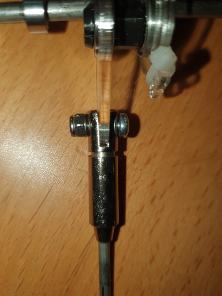
Tighten up the nuts so the armatures more freely on the con-rods. You may need to slightly bend the jaws of the armature apart with a screwdriver to allow this free movement.
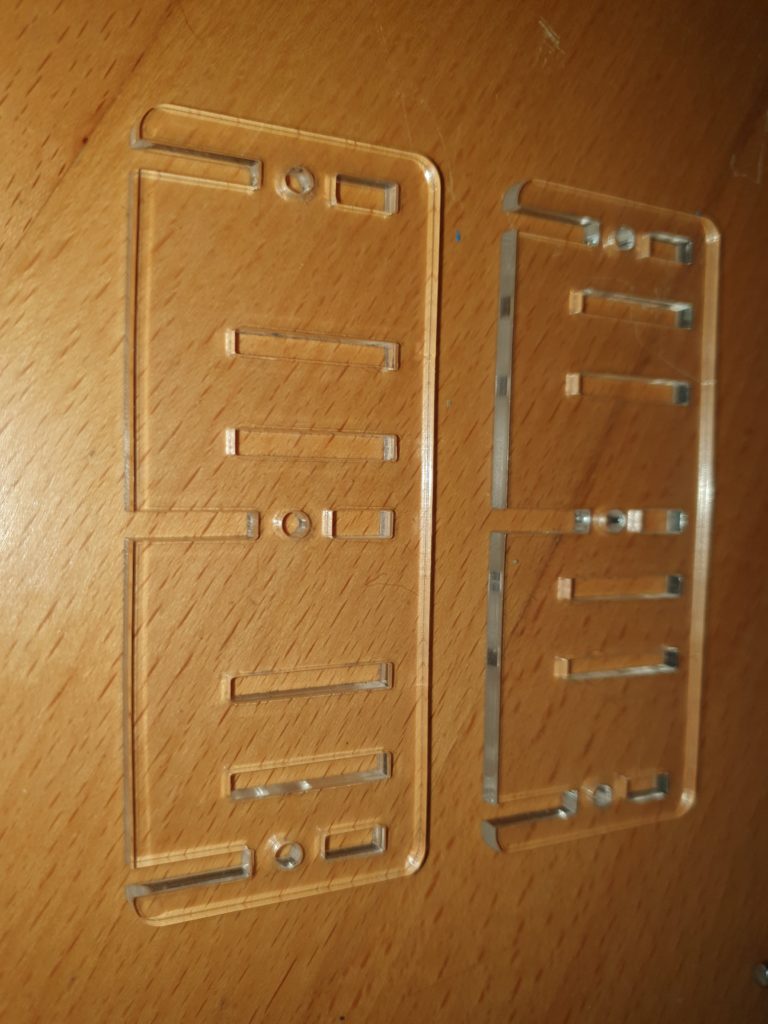
Take the two side pieces, and ensure they are different ways up. (note the position of the double slots.
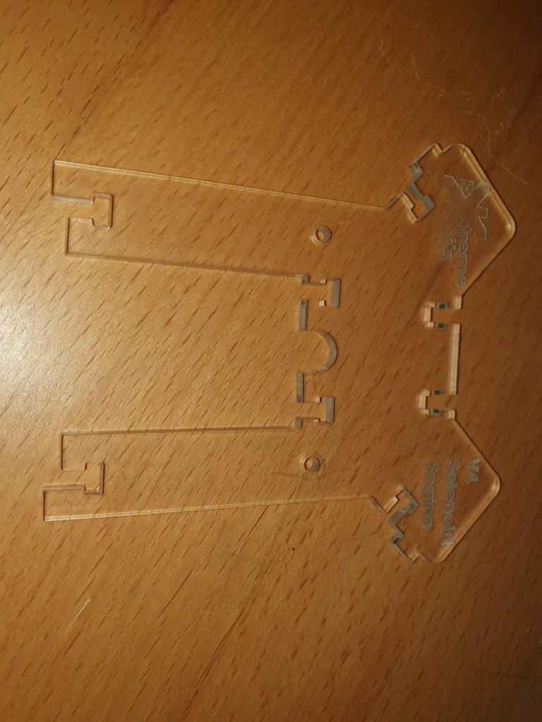
Take the front end piece (the one with the engraving)

and bolt on a side piece as shown with an m3x10mm screw and an m3 nut.
Tip: use a small magnet or a piece of Bluetak to hold the nut in place whilst you tighten the screw. Especially useful in confined spaces.

Repeat with the other side
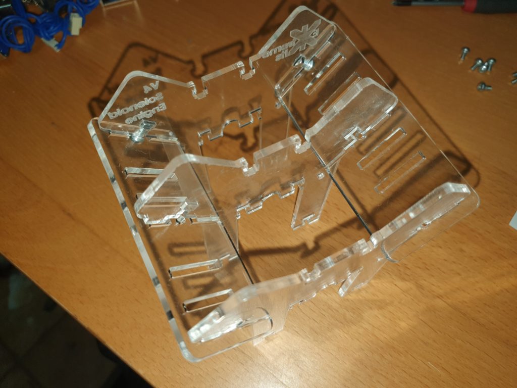
Slot in the other remaining middle and back pieces and screw together

Screw in the solenoids with the wide hole facing the middle with 2 x m3 x 6mm screws. Slide the solenoids to the rear (outer edge) of the slots to begin with.

All solenoids screwed in place

Turn the assembly upside down (solenoids downwards) and carefully feed in the armatures and axel into each solenoid. You may have to loosen or remove a solenoid to get it to fit in place

When the axel is in place secure the ball races into the slots in the clamp plates and secure with 2 x m3x10 screws and nuts. Be careful not to overtighten the screws and bend the clamp plates.

Stick the feet onto the base plate.

and screw in to the legs of the front, end and middle pieces with M3 x 10mm screws and m3 nuts.

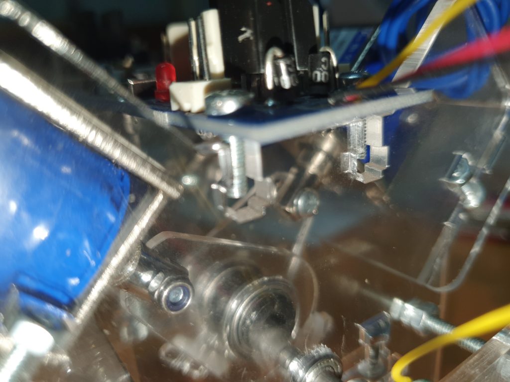
Using 2 x 10mm x M2 screws and two M2 nuts attach the position sensor to the acrylic carrier.
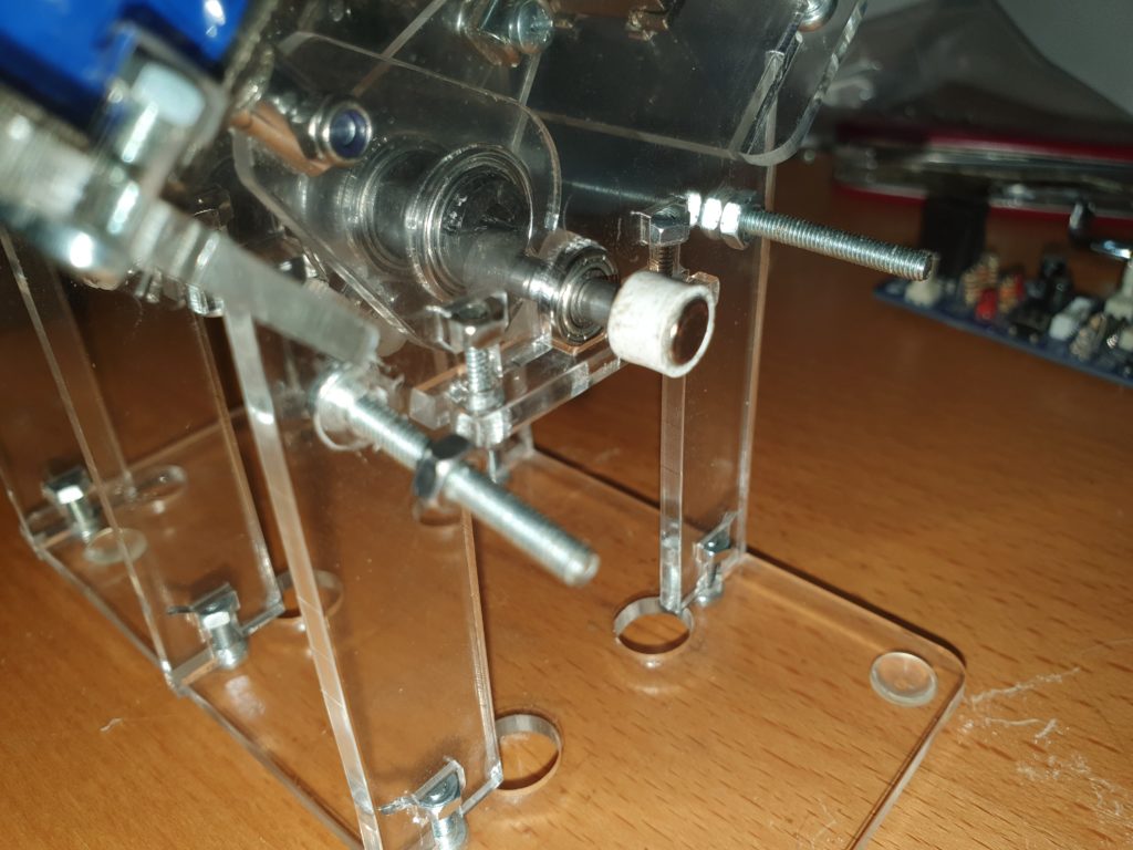
Attach 2 x M3 x 25mm screws in the rear end piece and tighten with 2 x M3 nuts. Add a second set of M3 nuts 5-10mm from the end of both bolts.
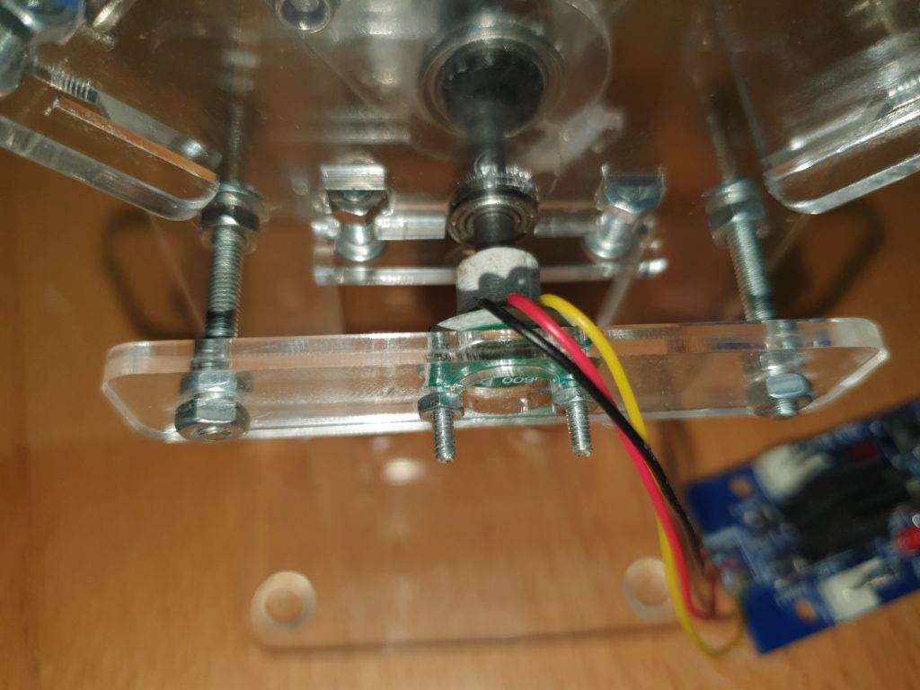
Place the position sensor/carrier onto two bolts with the IC facing, but not touching the magnet. The ideal position is for the magnet to be 1-2mm away from the top of the chip.
Adjust its position with the two m3 nuts and secure with two more M3 nuts.
Secure the PCB to the frame using 4 x M3 x 10mm bolts and M3 nuts.
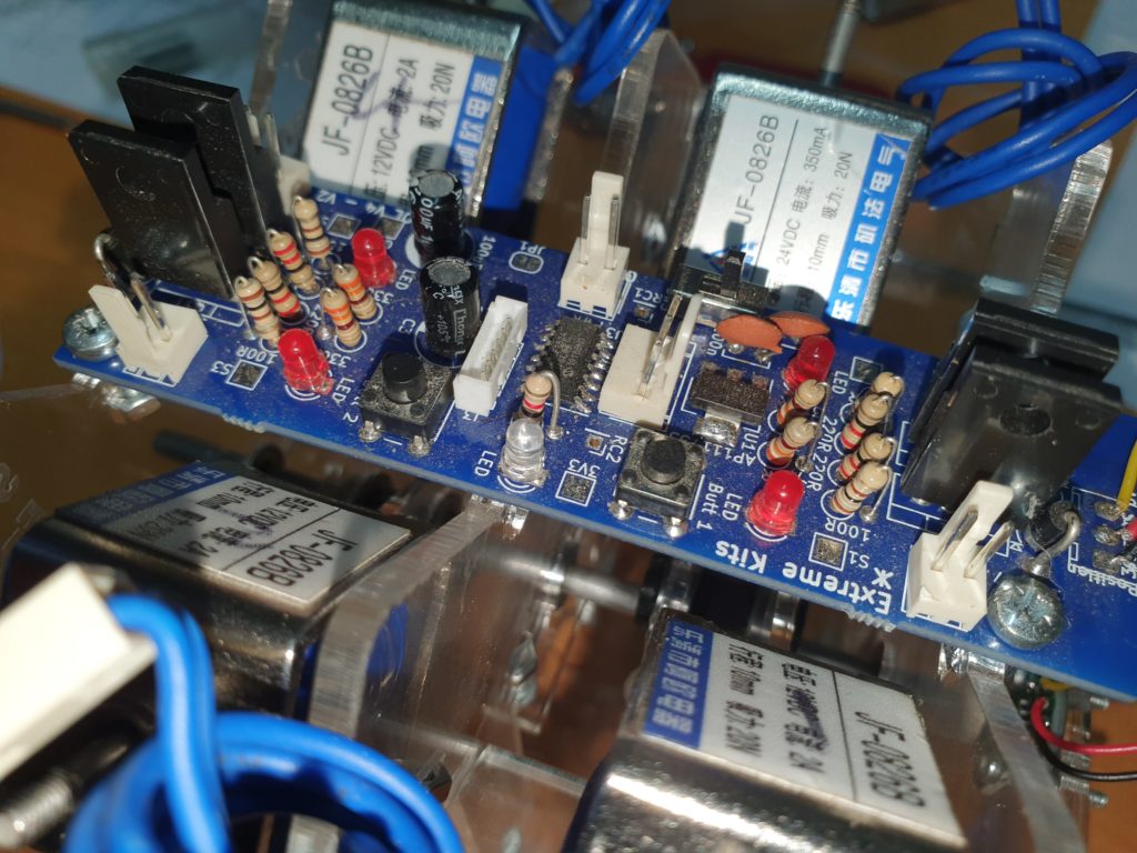
Plug in each of the solenoids to their nearest connector on the PCB.

With the spare M3 domed nuts that you took off the solenoids, place them back onto the exposed ends of the solenoid armatures.
