The morse kits are fairly simple circuits, but each component is important for its operation.
The Battery
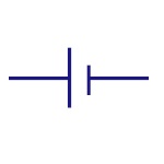
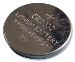
This powers the circuit. This particular type of battery is called a button cell. In this cell has a voltage of 3V this is a measurement of how hard the electricity is pushed around around the circuit. On one side of the cell is a + this indicates the direction that the electricity will be pushed. The other side of the battery is – this terminal pulls the electricity towards the battery. To complete a circuit both the +ve and -ve need to be connected to pull and push the electricity around the circuit.
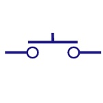
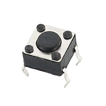
The Button
The button disconnects (breaks) the circuit, when the button is pressed this allows the electricity to flow. Although the button has 4 legs, 2 are joined together on each side making only two connections.
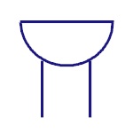
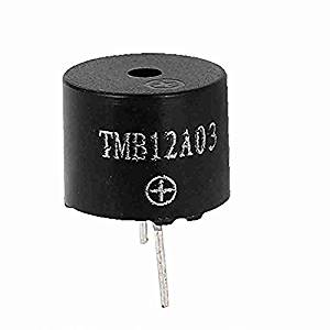
The Sounder
The Sounder is a component that makes a noise when it has electricity flowing through it. It will only work when the electricity flows through it in the right direction. There is a + labelled on one of its connections which must be connected to the + of the battery for it to work.
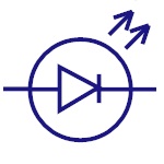
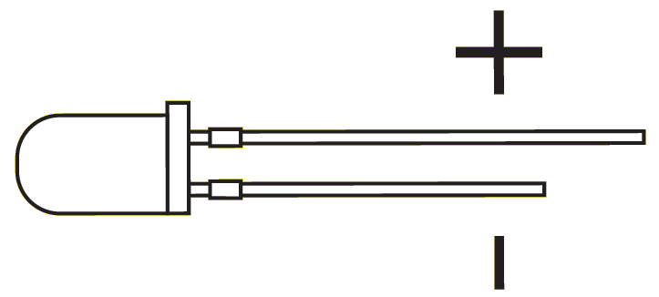
The LED (Light Emitting Diode)
The LED will light up when electricity is flowing through it in the right direction. As the LED is so small there is no + label to show you which way around it needs to be. On the LED this is shown by a flat side nearest the – wire and the longer wire of the LED is the + wire.
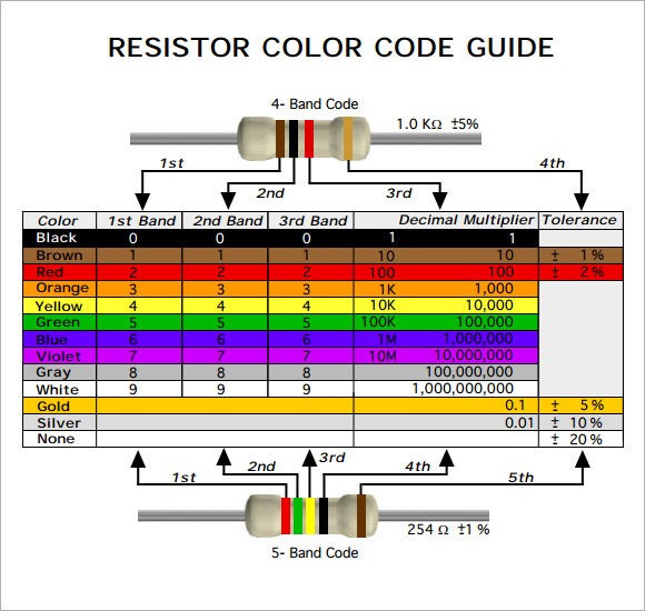
The Resistor
The LED is quite a sensitive component. If too much electricity flows through the LED it will be damaged. To prevent this we use a resistor. The resistor is like a kink in the electricity “pipe” it reduces the flow of electricity. Resistors come in many sizes and these are marked by the rings of colour around the resistor. The details are here.
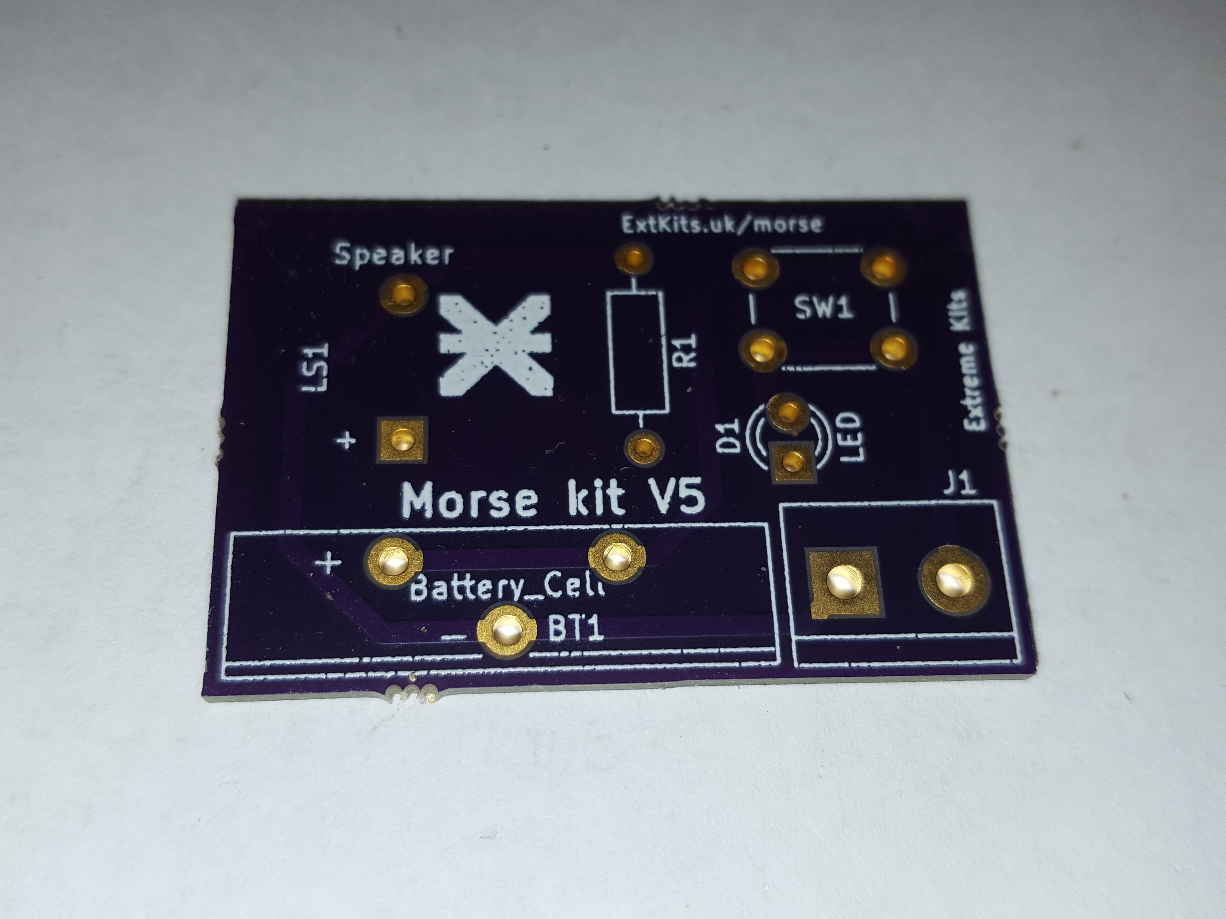
The Circuit board
The Circuit board hold all of the components together and provides copper tracks to connect them to the design on the circuit diagram.
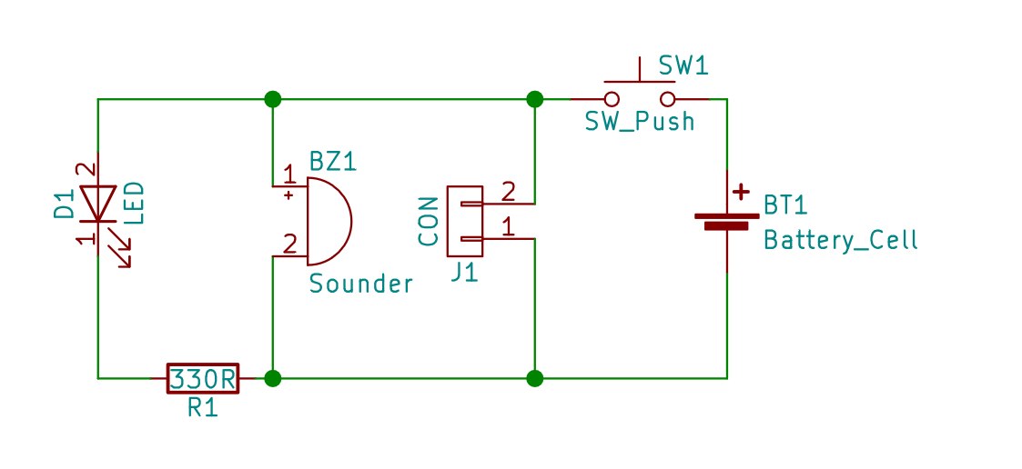
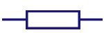
Circuit Diagram
The Circuit diagram is a map describing how all of the components are connected. A line between the component symbols indicates that they aught to be connected.