The Theremin
The Theremin was created by Leon Theremin (Lev Sergeyevich Termen) around October 1920 after noticing that a high frequency oscillators would change their frequency when a hand (or other object) was brought close to them. He added a circuit to make this change audible as a change in pitch of audio tone.
After demonstrating his ability to play notes and music on this device that he initially called the etherphone but over time became to be known as a Theremin.

Where have I heard it ?
Theremin music is heard usually as an accompaniment in many 1960’s and 1970 songs, but it’s most popular use was probably in horror or Science fiction films.
The Theremin had two ariels each with its own high frequency oscillator, one (usually the ariel sticking up) controls the pitch and the other (usually out to the side) controls the volume. The two ariels are set at 90 degrees to each other to reduce the possibility that the signal from one could affect the other.
The Theremin works as the proximity of the users hand changes the frequency of the oscillator feeding the ariel by adding capacitance to the circuit. The output from another oscillator set to a similar frequency as the first, but fixed, is mixed in to this signal and the resulting output is an audio tone. (the difference between the two frequencies)
More modern Theremins have various filters and synthesisers that can be applied to this basic tone to give different sounds.
The problem with this way of detecting the position of the users hands is that the oscillators need to be calibrated each time before use, and have a tendency to drift in frequency when the device is moved, or with changes in temperature and/or humidity.
Light Theremins
Due to the expense and tuning problems with a “real” theremins a number of “light” theremins have been produced. These all use some form of light sensor to detect the position of the players hands, but all suffer the same problem they are sensitive to changing light conditions and have very restricted range of detection.
Time Of Flight Sensors
Recently the cost of these Time Of flight Sensors (TOF) have plummeted and have made a new type of Theremin possible. The TOF sensors are small lasers combined with a very fast photodiode, these clever little devices are able to measure the time that the light from the laser takes to your hand, be reflected, and received by the photodiode. Even more impressive they can do this with millimetre precision. Plus, this is very accurately repeatable.
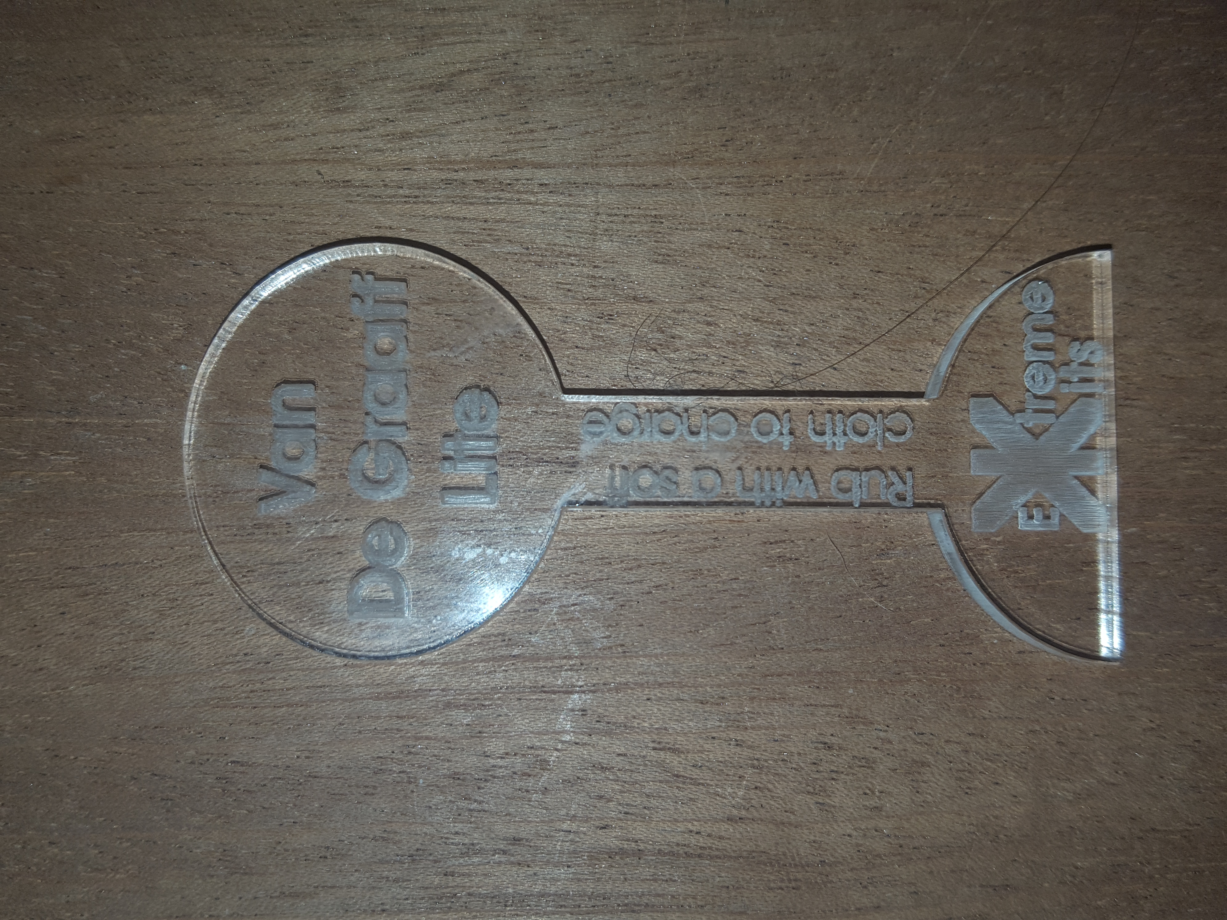
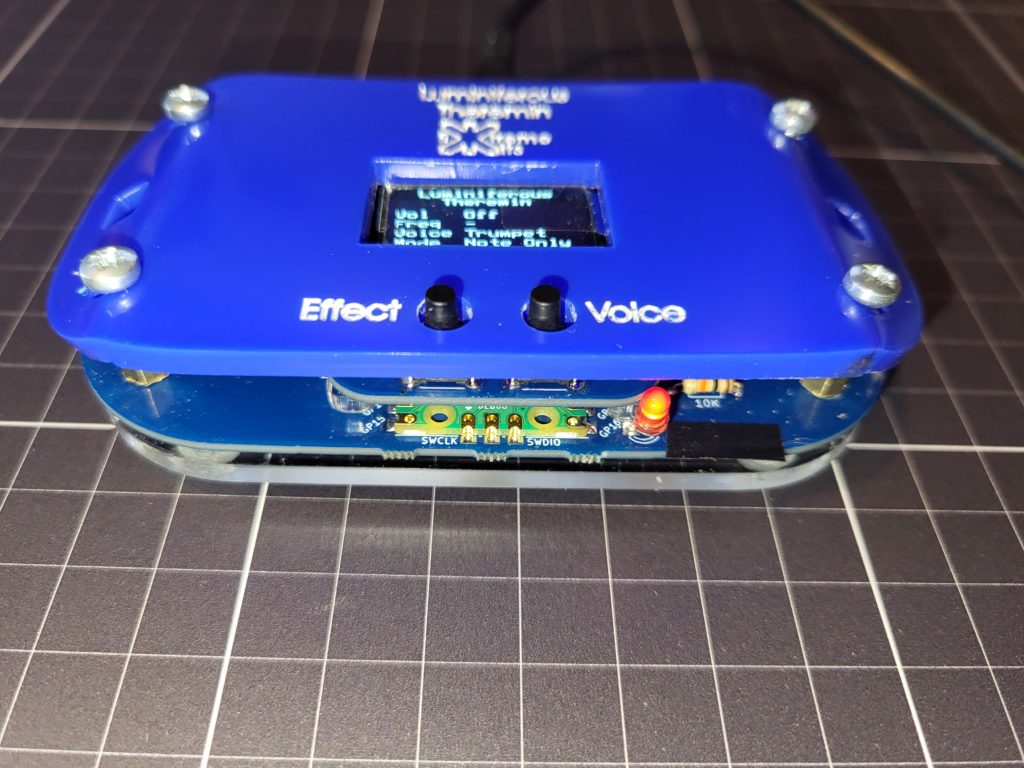
The Luminiferous Theremin.
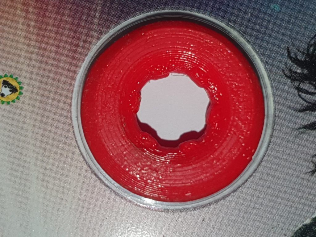
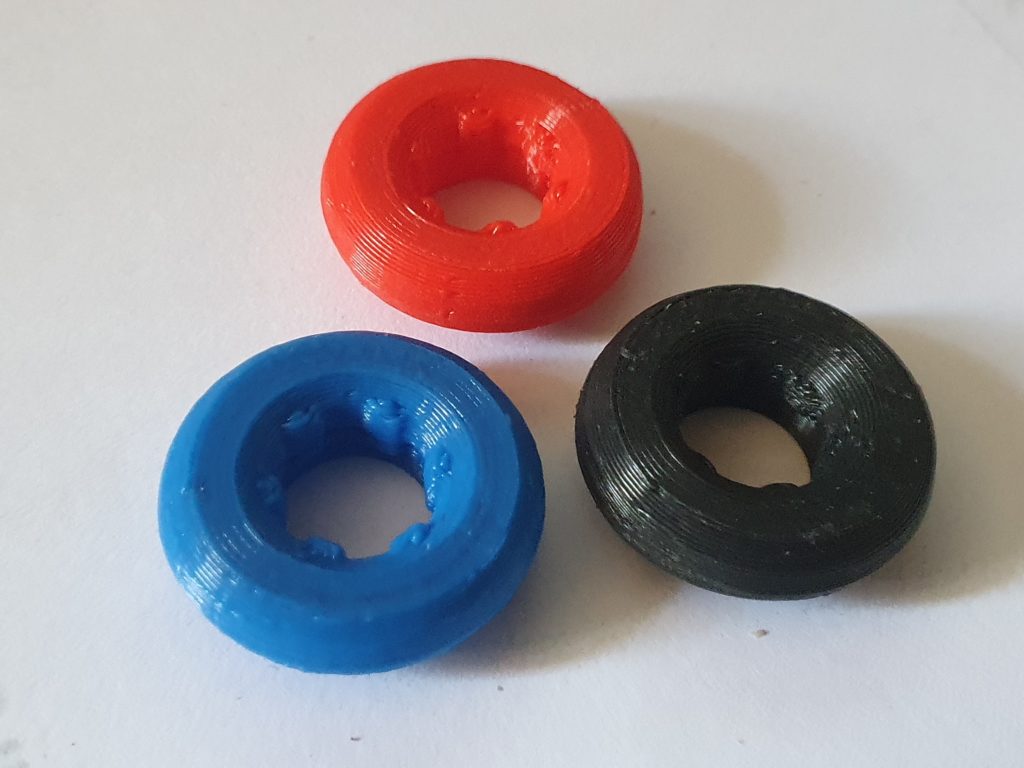
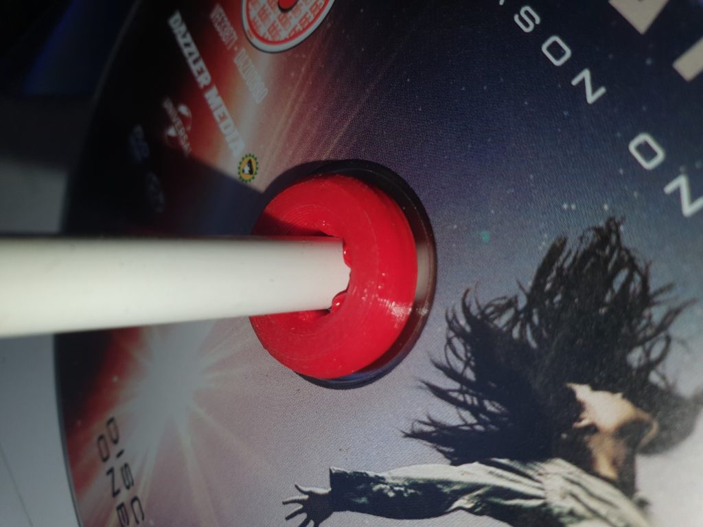
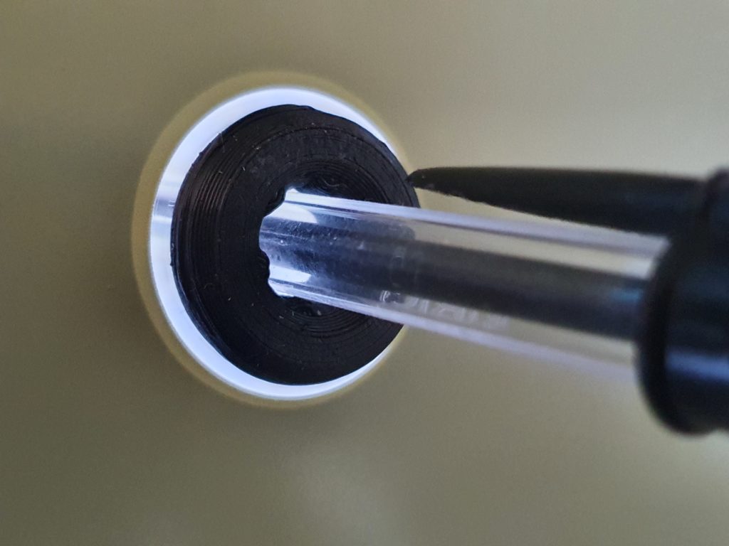
The Luminiferous Theremin is a small kit that uses two of these TOF sensors to create a modern day Theremin. Because these sensors are accurate and rely on the measurement of the reflection of light, there is no calibration, no problems with interference from either radio or other light sources. Another great advantage it is size, as there are no ariels it can easily be put in a pocket for transport.
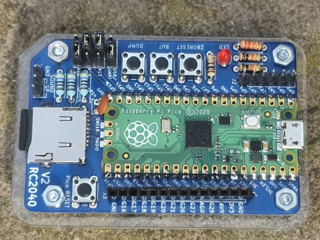
The other advantage with being 100+ years after the invention of the Theremin is microprocessors. Within the Luminiferous Theremin is a powerful microprocessor that can transform the distance measurement from the sensors into a wide range of sounds, not just the sign wave that the original Theremin can produce.
And, there is more to come, the project is being worked on to give more features as ideas are suggested the software is open source an can be viewed in a github and the board software can be updated easily.
Why Luminiferous Theremin ?
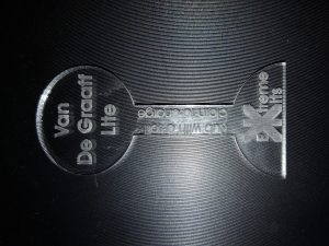
So, you remember the name of the first Theremin ? The “Etherphone”, The ether being an old reference to the “space” that radio waves travelled in, the aether.
The Luminiferous aether was an old name for the medium that light travelled in, and so an ideal name for a Theremin that uses lasers 🙂
Links
Luminiferous Theremin Resources
Other References:


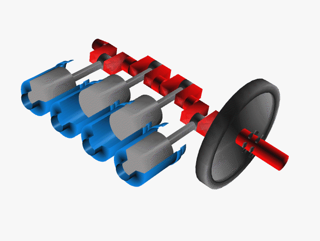
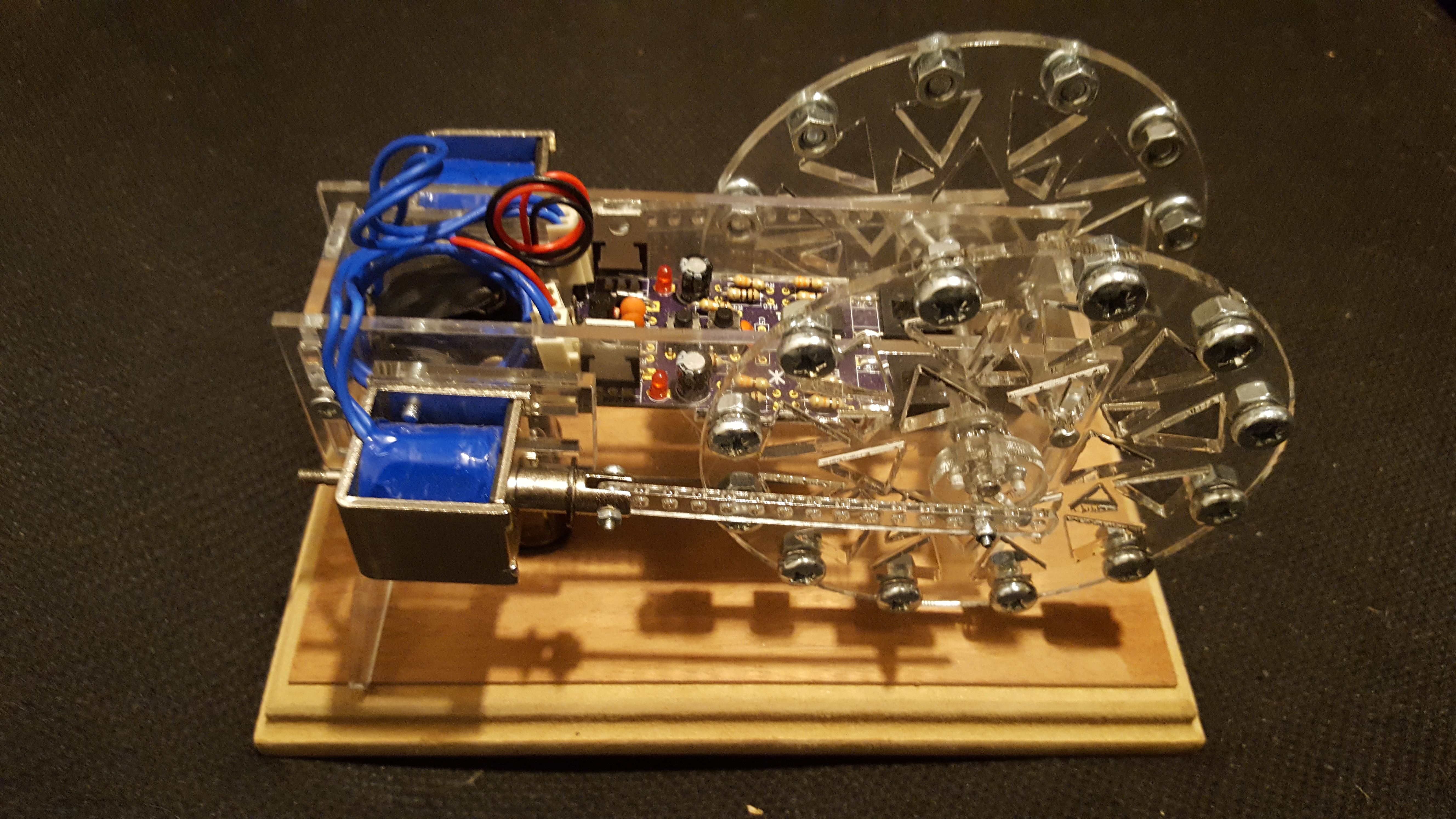
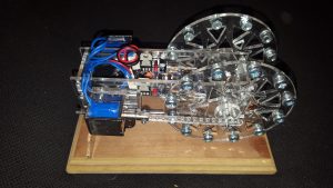
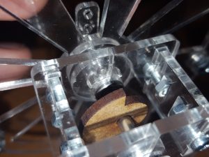 It has been replaced with a can and slotted opto, this method is much more reliable and easier to set up. As the axle now needs to move rather than be fixed, it also gave me the opportunity to bring out the engines output to the back of the motor so it can be used to drive some other kits (watch this space) .
 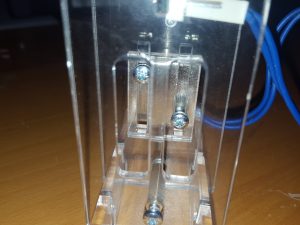 The mount for the solenoid has changed this gives two advantages. The screws for the solenoids are now easily accessible to move the solenoid for setup and the con-rod now connects to the centre of the solenoid armature meaning that the motor will run more smoothly.