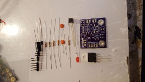
 The peices for the RPI/Micro:Bit solenoid engine interface
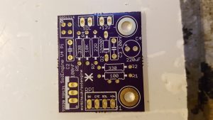 Take the PCB first and make sure it is clean and dry. This is the Component side
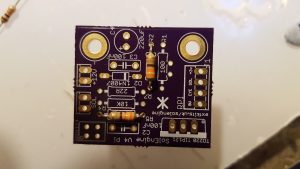 First add in the two 330 Ohm resistors (Orange,Orange,Brown)
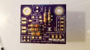 Then add in the 100 Ohm Resistor (Brown Black Brown) and 22 Ohm resistor (Red Red Black) and the 10K resistor (Brown Orange Black)
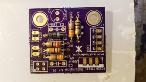 Add in the Diode, ensure it goes in the right way around, make sure the stripe on the diode matches the one on the PCB
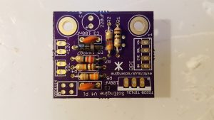 Add in the two capacitors.
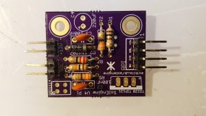 and Solder the three angle connectors into place as shown.
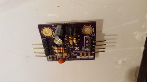 Add in the electrolytic capacitor and ensure the ‘-‘ labelled stripe goes to the outer of the board.
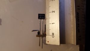 Set the opto-detector 15mm from the surface of the board. Also ensure that the dot on the edge of the detector matches the dot on the PCB ident.
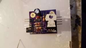
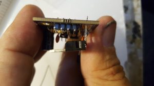 Place the transistor on the board and solder in, bend the transistor over 90 degrees as shown.
 Solder the LED on the rear of the PCB, ensure the flat side of the LED is towards the “PULSE” on the PCB.
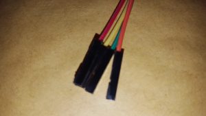 Insert your 4 leads into the PI J1 connector
