
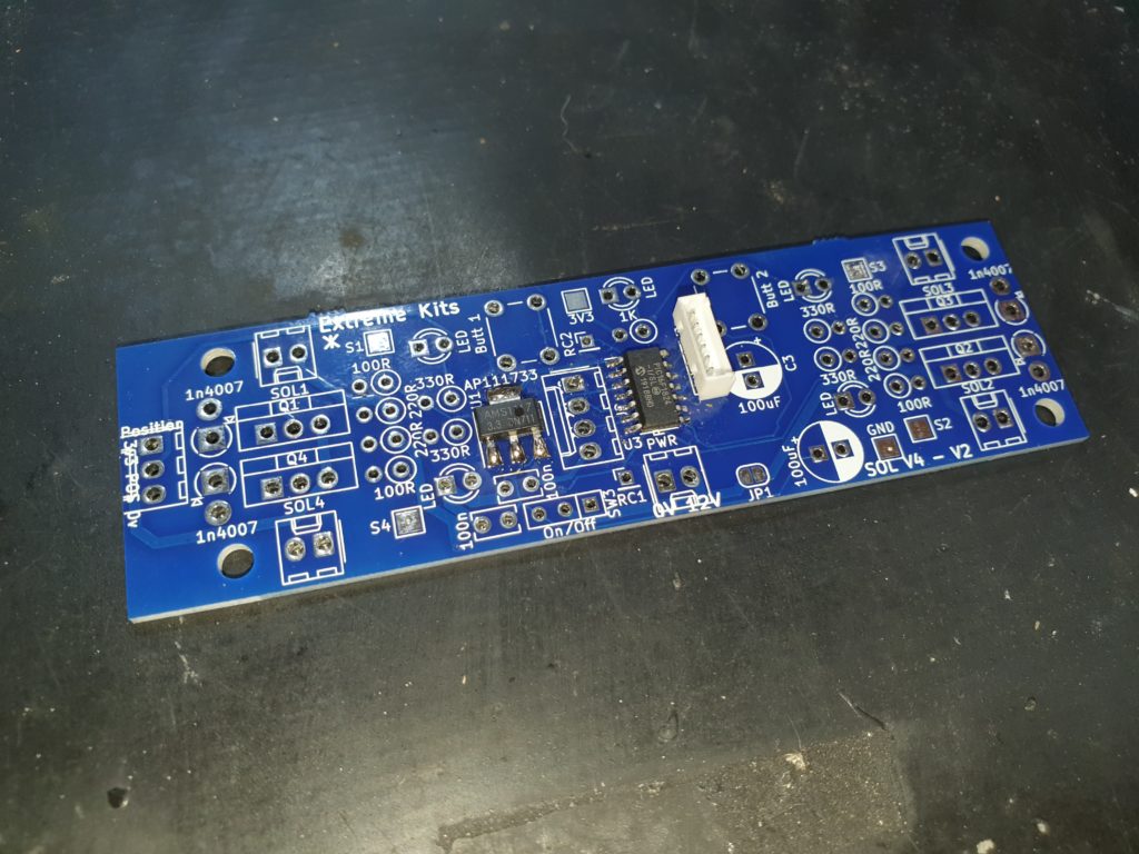
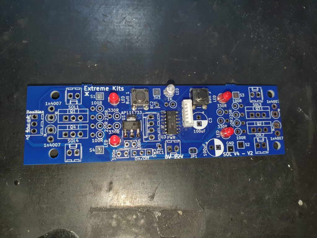
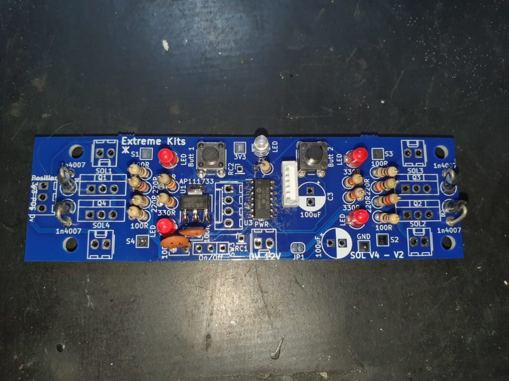
First solder in the micro processor, ensure that pin1 on the chip (the dot) matches the ident on the PCB . If you are unsure compare it to the photo.
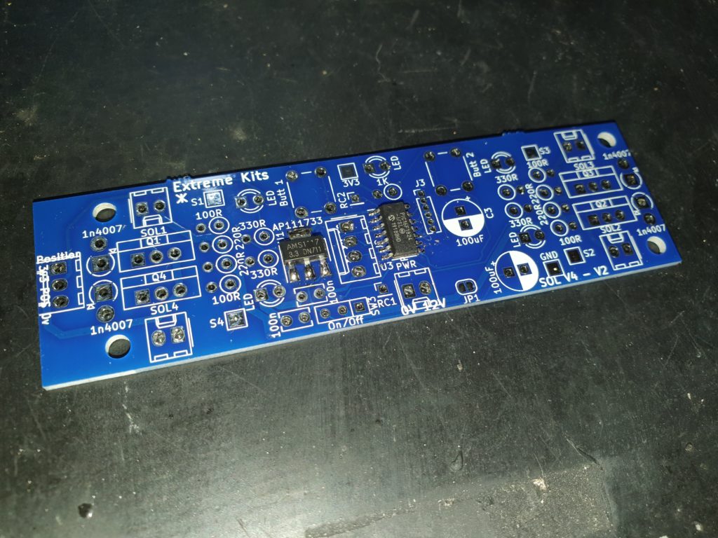
Solder in the 3.3v Regulator
Optional
If you are interested in reprogramming the processor you may want to add in this 1.25mm header.
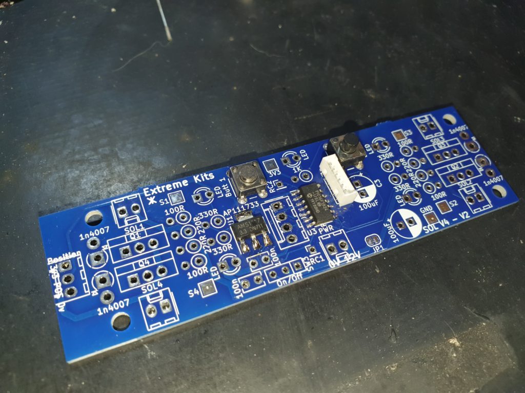
Solder in the two push buttons
Solder in the 5 LED’s The 4 red ones are for each solenoid and the green one is for the power.
The Short Leg of the LED needs to go into the square plated hole
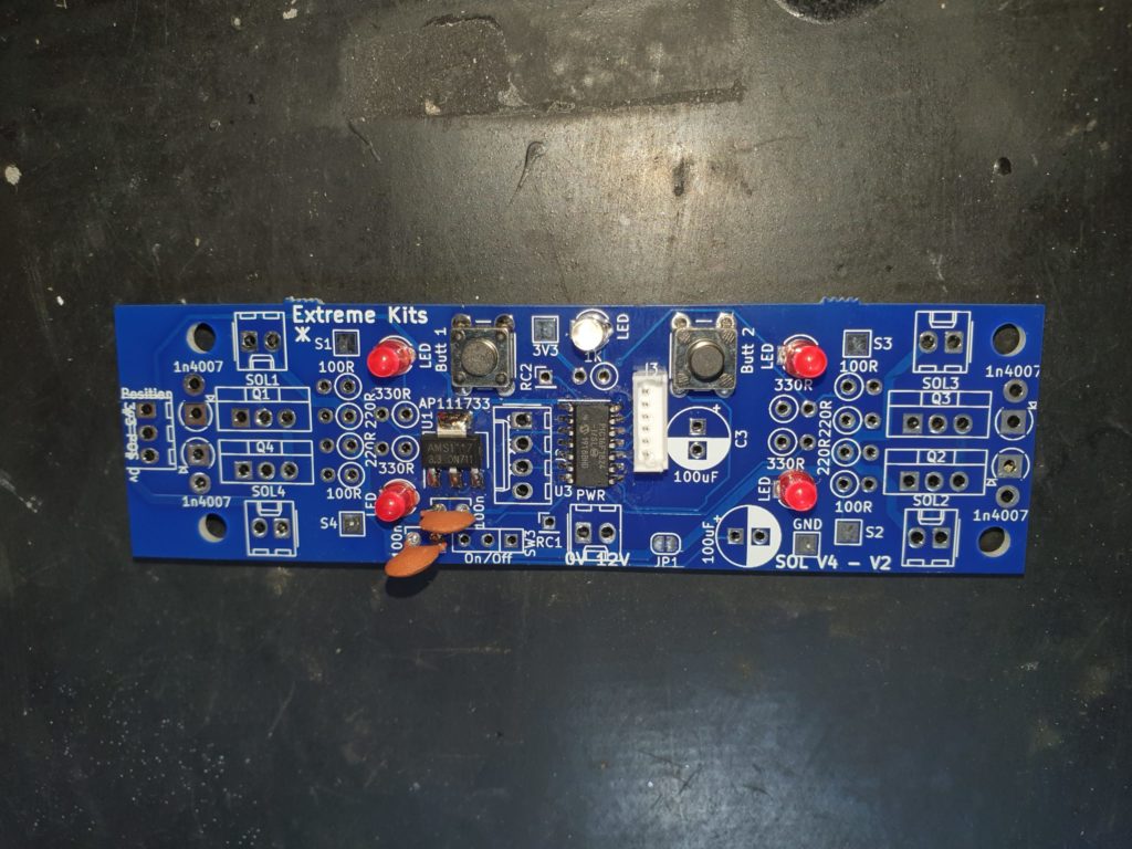
Solder in the two 100nF Capacitors
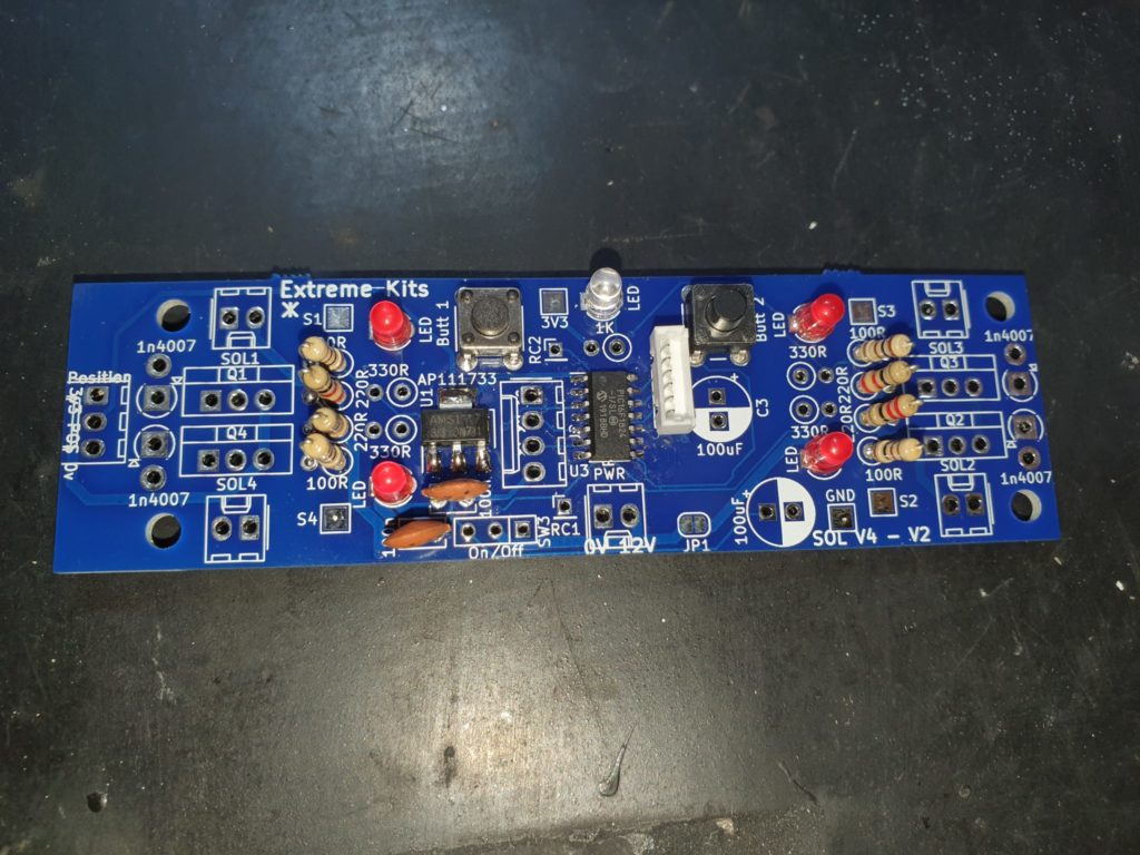
Solder in the 4 x 220 Ohm resistors (Red,Red, Brown) and the 4 x 100 Ohm resistors (Brown,Black,Brown)
Solder in the 4 x 330 Ohm Resistors (Orange,Orange,Brown)
Solder in the 4 diodes, ensure that the cathode (the white ring around the diode) points to the square plated holes in the PCB
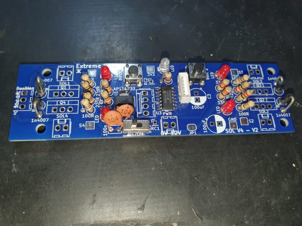
Solder in the On/Off switch
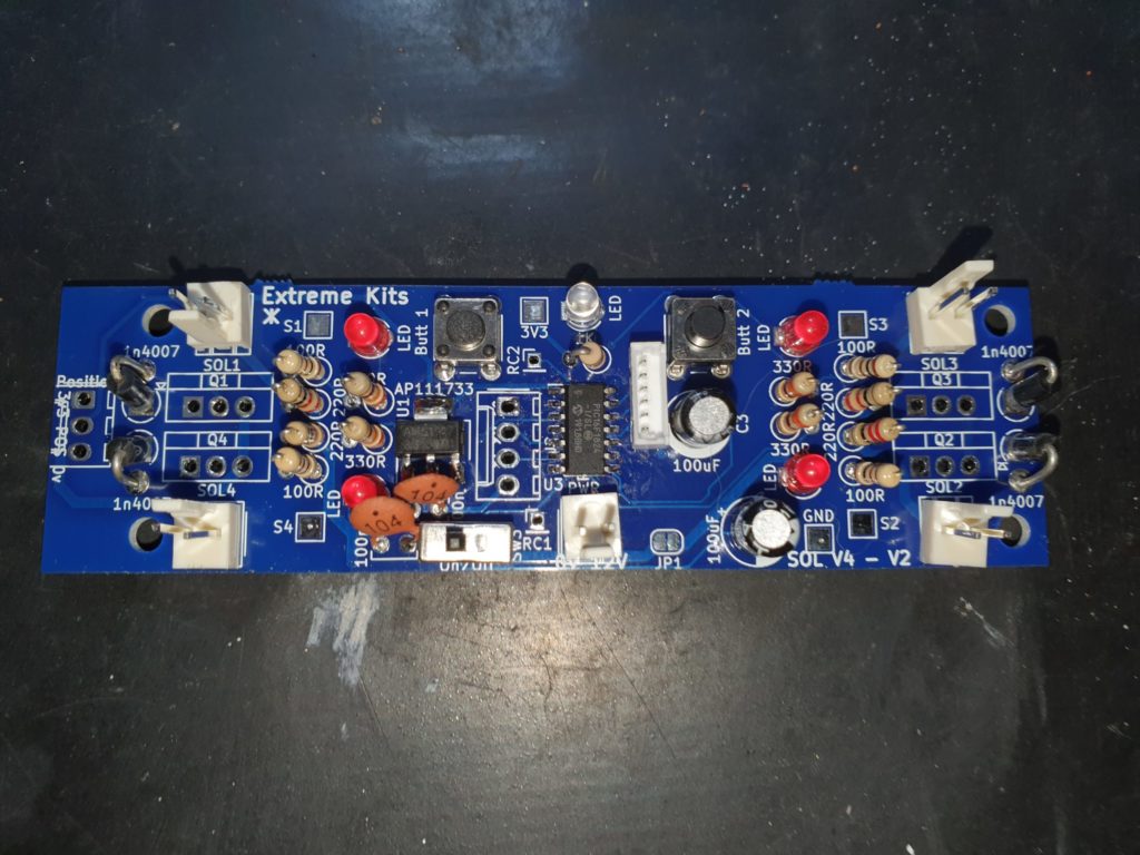
Solder in the 2.5mm header plugs, be careful to ge them soldered in the right way around, especially the power connector.
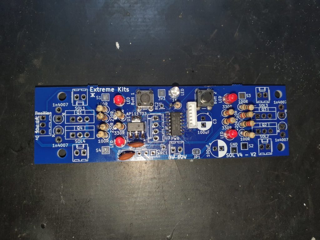
Solder in the 4 MOSFETS ensuring that they all match the PCB Ident and face the same way around.
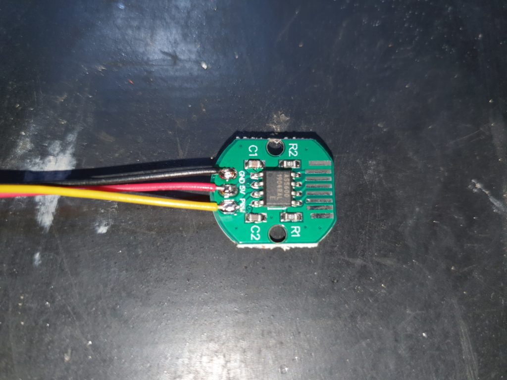
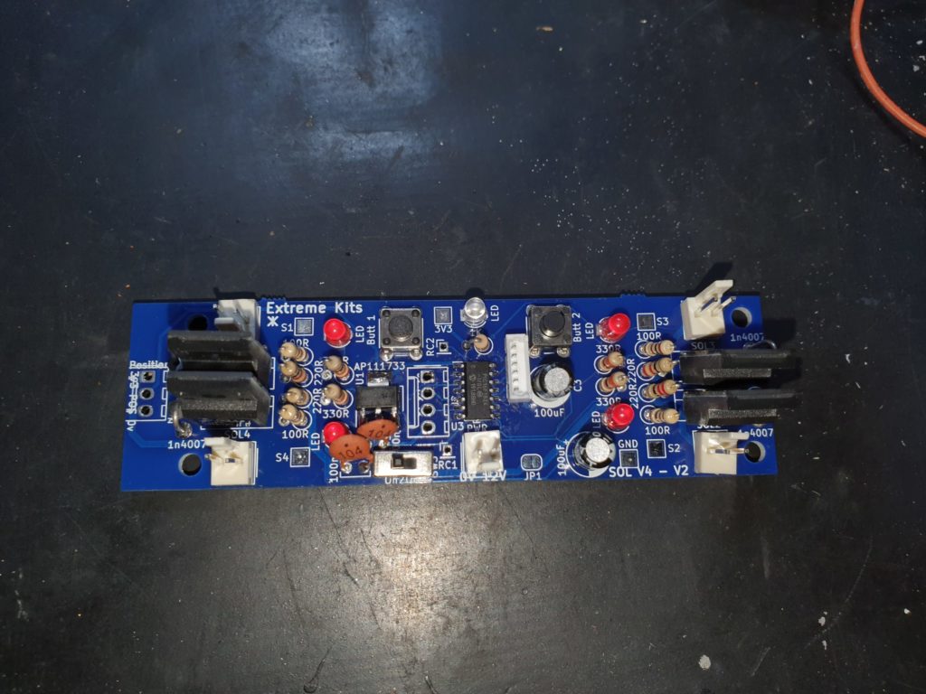
Solder on the wires to the position sensor PCB ensuring the colours are the same as in the picture.
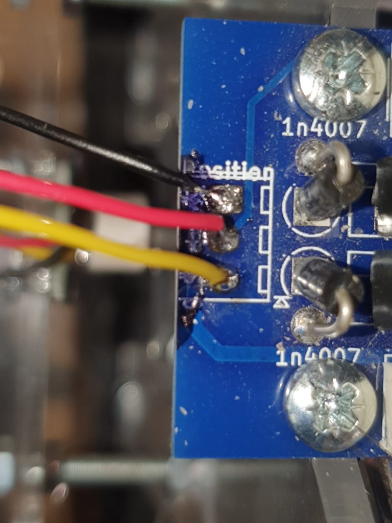
Connect and solder (hopefully better than I have done here ) the three wires from the position board. The Square pad is 0V, then +3v3, then position.
