
Construction of the mechanical parts of the Sol Engine
For this you will need a sharp knife, a small screwdriver, a small pair of pliers, a tray for the small parts and if possible an m2 nut runner (nice, but not vital)
 First take the back plate of the engine and screw in the 4 x M3x10mm screws and secure each with an M3 nut. These will hold in the PCB
 Mount the PCB onto the back plate, ensuring that the LED’s push through the holes in the back, secure with 4 x M3 nuts
 Add the solenoid to the front engine plate, ensureing the square hole is in the position shown.
 screw the solenoid on to the plate using 2xm3x6mm bolts.
 Place the front plate of the engine on to the back plate with the PCB sandwiched on the inside. Ensure that the front is the correct way around, by lining up the three holes in a row at the top on each plate. Connect the two pieces with two M3 x6mm screws and a M3 x 18mm standoff.
 Using 2 x M3 x 6mm screws secure two 18mm standoffs to the front plate. place the locking piece onto the outside of the back plate and using 2 x m3x10mm screws, screw into place.
 Take the flywheel, bearing axle,bearing plate, 4 x m2 x 8mm and 1 x m2x20mm bolt
 Place the bearing plate on one side of the flywheel and insert the bearing axle into the centre of the flywheel from the other.
 Bolt the bearing down to the flywheel using the m2 screws (4xm2x8mm and 1 m2x20mm) leaving the bearing sticking out by 1 mm on this side, the bearing plate should be flat to the flywheel.
 The five screws should be bolted into place tightly. Place two nuts on the m2x20mm screw. When complete the flywheel should run freely and true on its axle.
 Take the completed flywheel assembly and a sheet of aluminium foil tape.
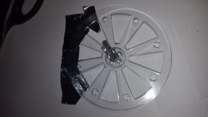 Cover three segments of the wheel on the axle side with foil tape
 The three outer segments that need covering are shown in the picture. Note the position of the m2x20mm screw sticking out from the flywheel. It is vital that the correct three are covered in relation to this screw. A black pen mark indicates the position of the 20mm m2 screw.
 Insert the axle through the middle hole of the engine plates, and twist the locking place to secure. You may need to slacken off the screws to do this, re-tighten them when the flywheel is secure. The flywheel should sit so there is a small gap between the plate screw heads and the flywheel screw heads allowing the flywheel to turn without catching.
 Attach the plunger of the solenoid to the push rod with a m2x20mm bolt securing it with an m2 nylock nut. Ensure there is some play between the two, don’t tighten the nut so the rod can’t move.
 Secure the other end of the push rod to the m2x20mm bolt sticking out from the flywheel with an m2 nylock nut. Adjust the position of the solenoid and push rod so that the plunger will move in and out of the solenoid without bottoming as the flywheel is rotated.
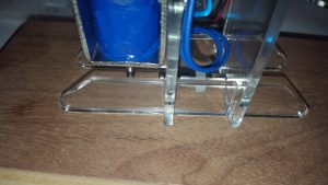 Carefully push on the two feet for the engine, you may have to loosen the screws into the 18mm standoff to make this fit easily.
For an extra smooth operation more weight can be added onto the flywheel by the addition of 8 M5 6mm screws and nuts (not included in the kit)
.
.
.
.
.
.
.
.
.
.
.
.
.
.
.
.
.
.
.
.
.
.
.
.
.
.
.
.
.
.
.
.
