
Building your buzz wire kit – Step by step instructions to make the electronics to include into any kids buzz wire project.
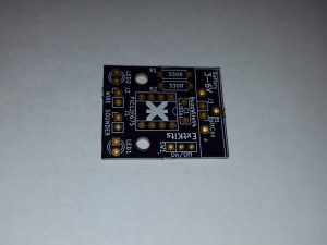 The bare Buzz wire kit board. Make sure it is clean, dry and free from grease on both sides .
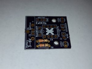 Fit the two 330 ohm resistors (Orange Orange Brown) into the holes labelled 330R as shown.
Again bend the legs back a little on the reverse side of the PCB to stop them from falling out and solder.
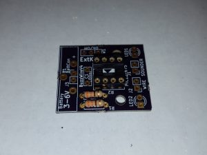 Place the 8 way IC holder into the position shown, Ensure that the cut-out in the holder, matches the cut-out on the board silk screen. Turn the board over and carefully solder the pins.
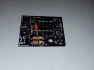 Put in the 0.1uF capacitor in invert the board and solder.
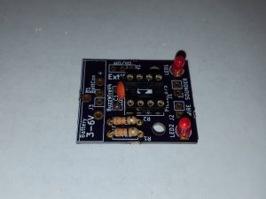 Place the LED’s into the two circles as shown, Ensure that the cut out side of the LED goes to the square pad on the board.
If you are unsure of the orientation the shorter of the LED legs should go to the square solder pad.
Bend the wires back to stop the LEDs from falling out. Invert the board and solder, cutting off the legs close to the soldered joint.
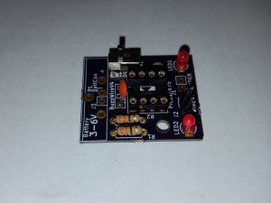 Inset the switch into the three holes towards the side of the PCB
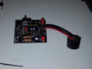 Solder the sounder into the holes labeled Sounder and For testing, solder two wires on to the two pads labelled “WIRE”
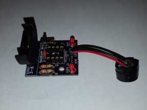 Add the battery holder and solder.
Insert the IC into the socket, ensuring that the cut out in the IC matches the cut out in the holder. Also ensure that all of the IC’s ‘legs’ have been pushed fully into the socket.
Insert the battery. Ensure that the battery + side matches the + in the socket
Turn the switch to the ON position
Touching the two wires together will cause the lights to flash and the sounder to warble.
Congratulations, you have a working BUZZ wire. If you have a great project built on this email me at info@extkits.co.uk