
Need photos…. Come back soon…
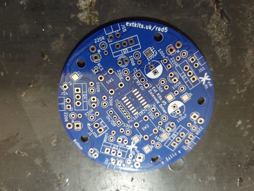
Solenoid engine Radial5 PCB, Ensure it is free from grease and dirt.

If your PCB already has the surface mount chips soldered on skip to here
Solder in the Processor IC ensure the pin 1 indent is top right as shown.
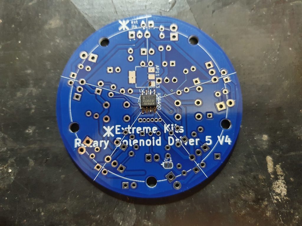
Flip over the board and solder in the rotational position IC again ensure the chip has the pin one ident top right.
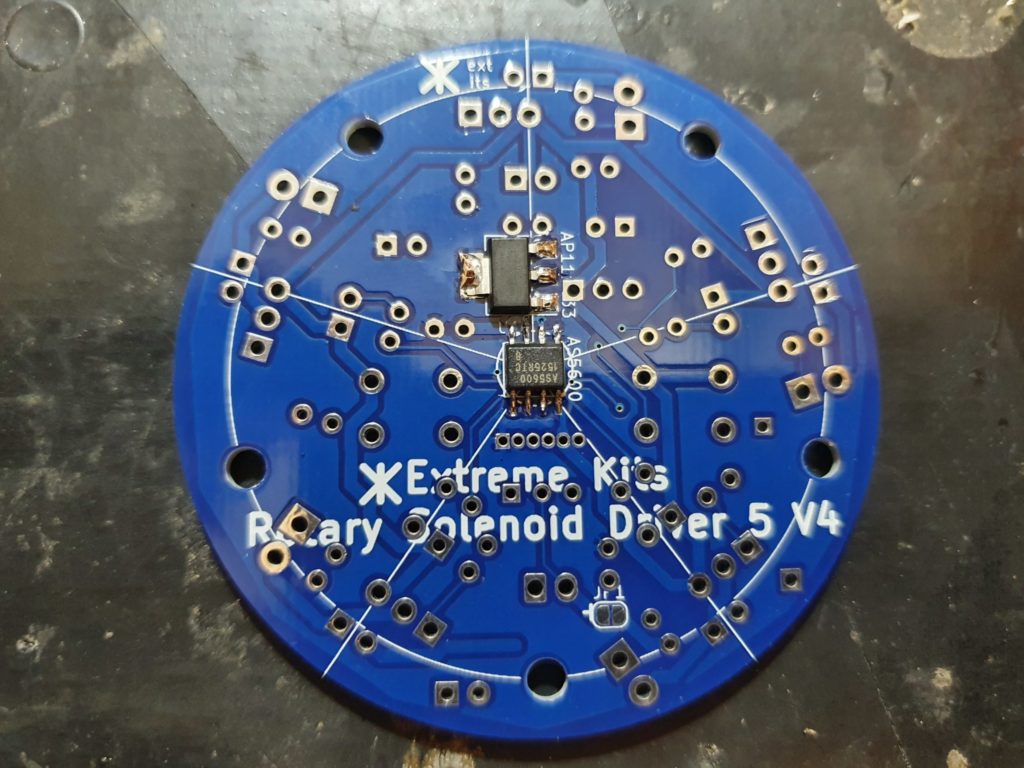
Solder in the regulator as show.

Flip the PCB back over and install the programming header ensure the header is the right way up, as shown.
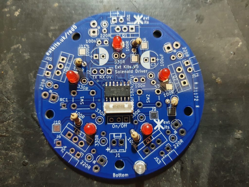
Through Hole Assembly

Solder in the 5 red LED’s Ensure the short leg goes to the square through hole on the PCB (or the flat part of the D shape in the base of the LED

Solder in the single Green LED again Ensure the short leg goes to the square through hole on the PCB (or the flat part of the D shape in the base of the LED
Solder in the 5 x 100 ohm resistors (brown,black,brown)

Solder in the 5 x 220 ohm resistors (red,red,brown)

Solder in the 6 x 330 ohm resistors (orange,orange,brown)

Solder in the 5 x 1n4007 diodes. Ensure the Cathode (white ring) is soldered to the square through hole.

Solder in the 2 x push buttons.
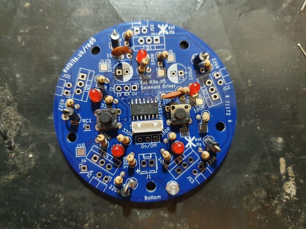
Solder in the 2 x 100nF capacitors.
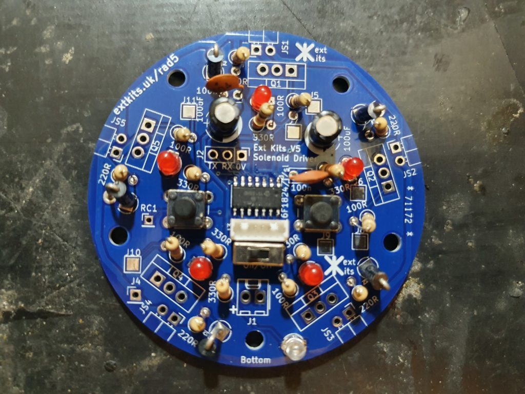
Solder in the 2 x 100uF Capacitors, ensure the white -ve stripe matches the white semicircle on the PCB
Solder in the switch.

Solder in the vertical 2.5mm power connector, ensuring the tab is towards the top of the PCB as shown
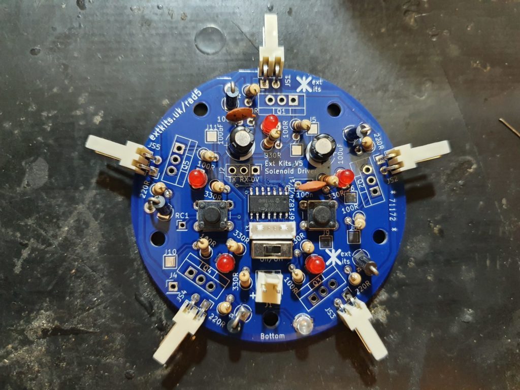
Solder in the 5 x Horizontal Solenoid Connectors as shown.
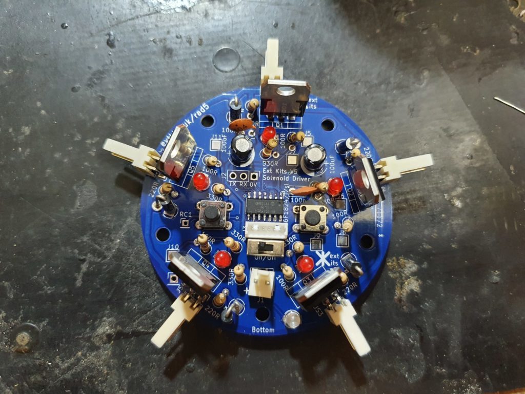
Solder in the 5 x Power transistors, ensuring that the flat side of the transistor is towards the centre of the PCB as shown.
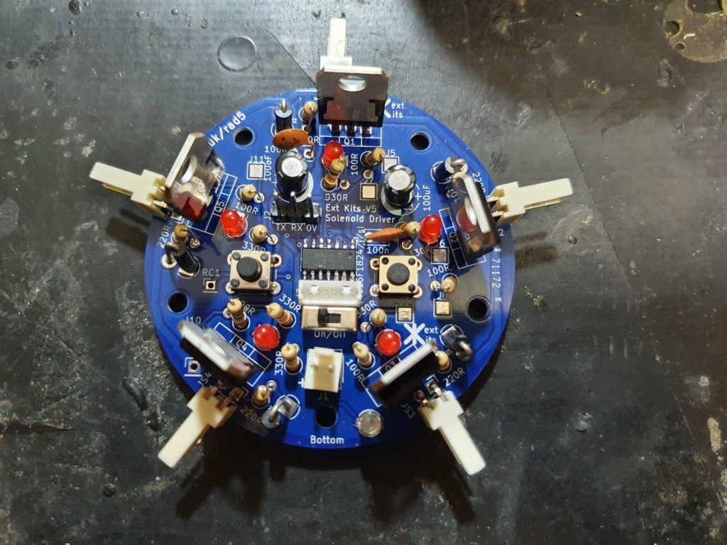
Solder in the 3 way 2.5mm serial connector.
