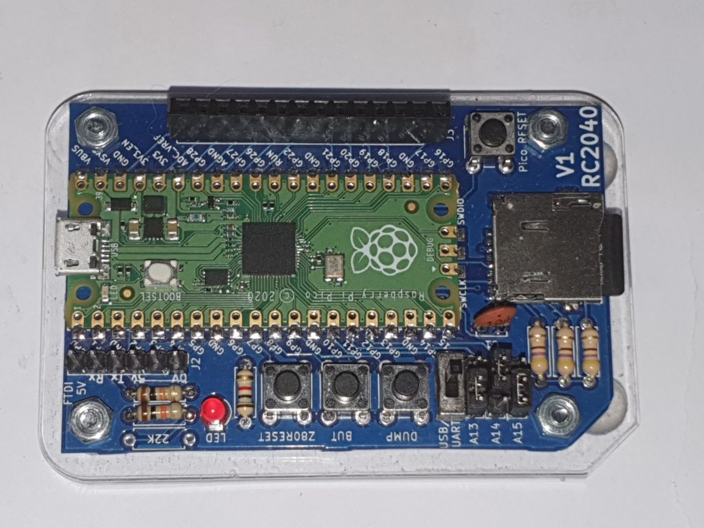
PCB,
Populate the PCB using the component idents on the PCB
Take special care that the SD card holder is flat to the PCB and ensure that none of the pins are shorted when soldering. Start by soldering the 4 metal shield points first ensuring all of the pins line up with the pads.
If you are not used to soldering surface mount components. I’d suggest you get some no-clean PCB flux and coat the SD card connections. Use the finest soldering iron bit you have and the thinnest solder. Then carefully apply solder to each PCB pad and let it run up to the pin.

Please use this picture for further reference. If you have a 2.5mm pitch switch you can replace the usb/uart header above for easy switching. Please also note the 22K resistor should be soldered in (I realise it’s missing in the picture above)
Software
For Software and instructions for programming the PICO Take the latest release from the Git Hub here
Thanks to work done by Guido Lehwalder , This kit now has software support for RunCPM as well as the CP/M-80 / RC2014 emulation, the source & binary is available at https://github.com/guidol70/RunCPM_RPi_Pico
Please note: I’m unable to give any support for RunCPM)
More details
Can be found at https://www.extremeelectronics.co.uk/the-rc2040-get-you-started/
This project is still a work in progress. Check back to the Git Hub for future developments.
