
Tools needed
Fine tipped soldering iron & solder
Cutters
Tweezers
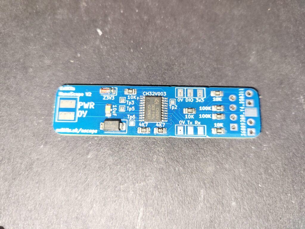
Take the surface mount PCB, for the through hole components that you will be soldering, this is the bottom side.
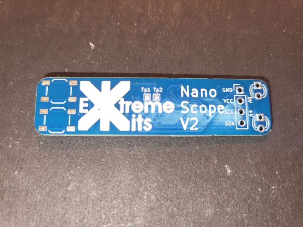
This is the top side of the PCB, this is where you will be soldering the components.

Carefully tin the PCB on one of the four pads for each of the buttons. Take one of the two push buttons and (possibly with the help of a pair of tweezers) place the legs of the buttons over the pads on the PCB, gently heat the leg that is over the tinned pad so the solder flows.
Repeat with the second button.
When you are happy with the position of the buttons, solder the other three legs on each button.
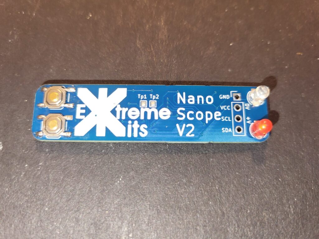
Solder in the two 3mm LEDs flush with the PCB.
The Green LED needs to go next to 0v, and the red LED need s to go next to +V
On V2 PCB’s – The longer lead of each LED, needs to go to the square pad on the PCB. [Yep, I put the LED’s the wrong way around in the schematic 🙂 ]
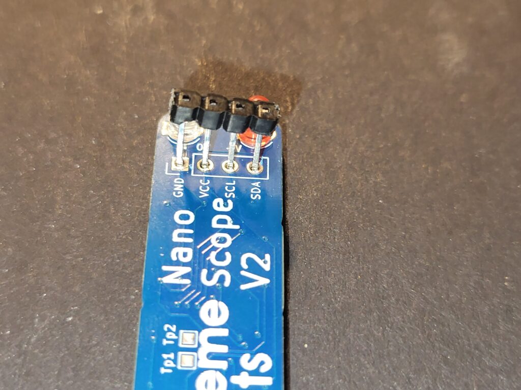
Solder in the 4 way header, and after it is soldered in, carefully remove the black spacer. (on some displays, the header is already soldered on to the display, Carefully remove the spacer, but be careful not to stress the glass on the display.)
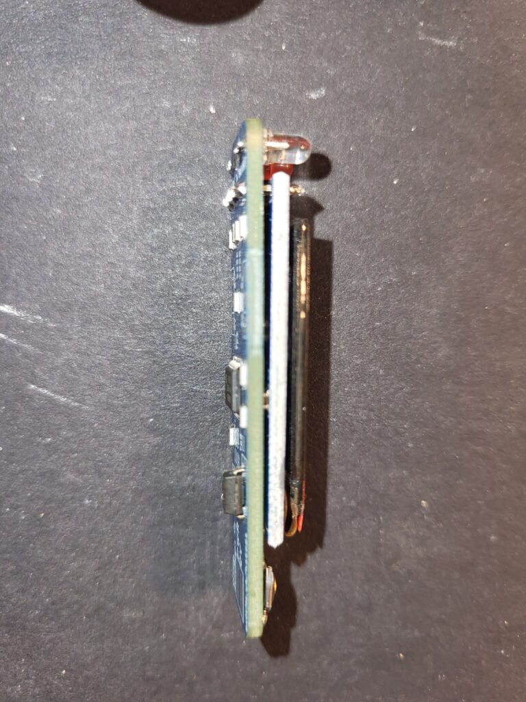
Solder in the display, and cut off any excess leads.
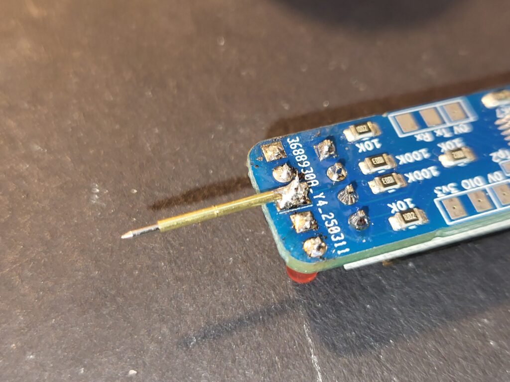
Solder the pogo pin to the middle pad between the LEDs.
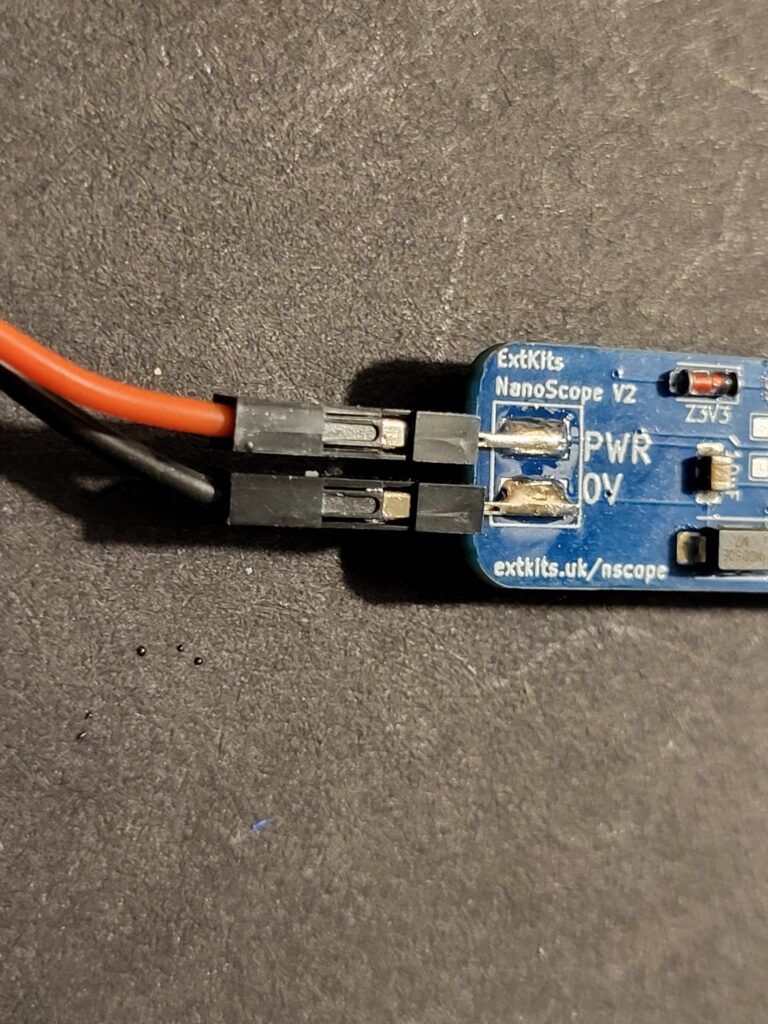
Solder on the two power leads. (If you have a case these need to be soldered on after the PCB has been fitted into the case.)
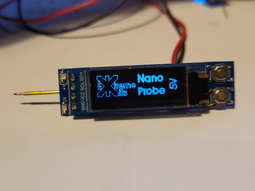
You have completed your nano probe.
Please read using your nano probe before powering it up
