
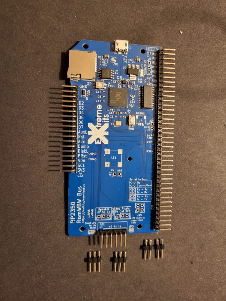
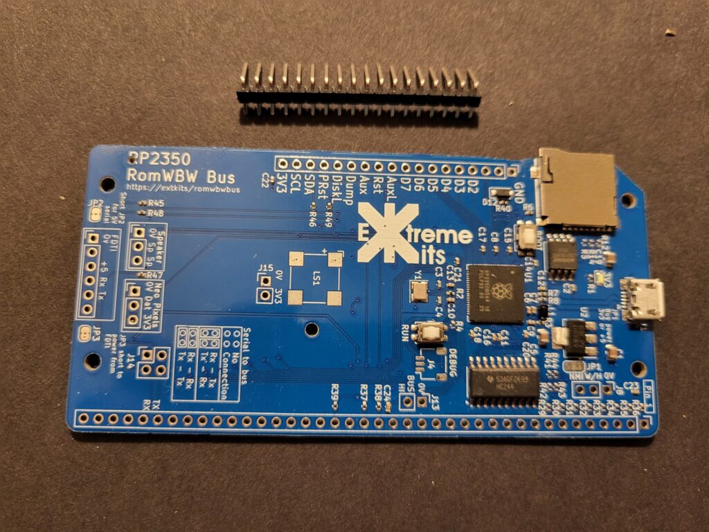
Break out the PCB and file off any remaining mouse bites.
Do NOT solder in the bottom connector, until later in the build….
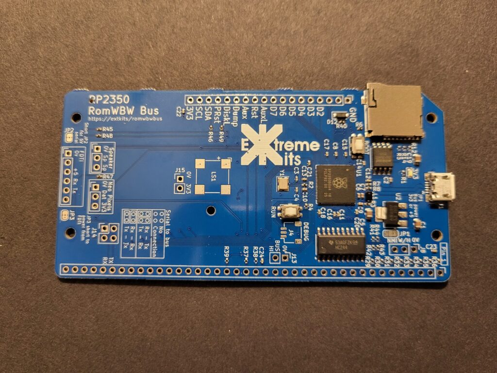
Solder in the FTDI connection (6 way 90 degree header)
Do NOT solder in the bottom connector, until later in the build….
Solder in the Neo-pixel, speaker and RS232 jumpers.
Also solder on the speaker, ensuring that the + aligns with the + on the PCB ident.
From here there are two ways you can build your kit.
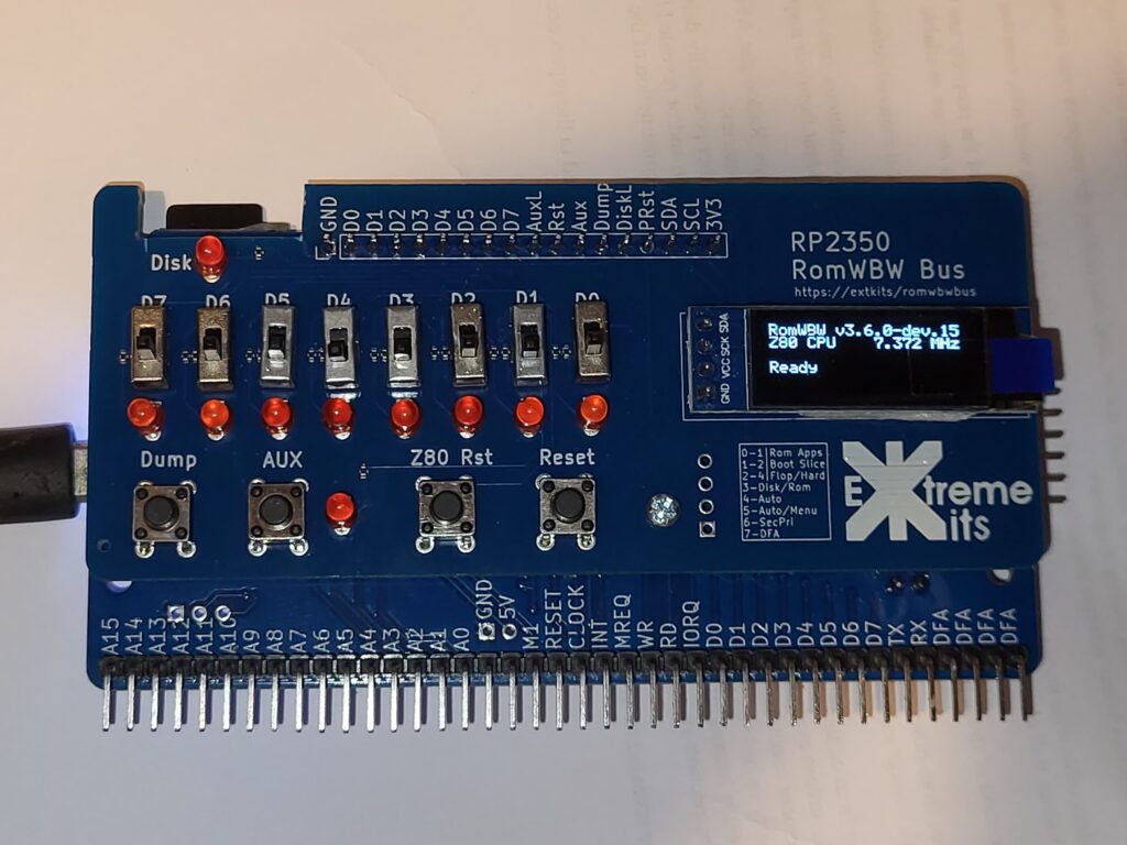
Either as a Boxed kit, with the RC2014 bus connector at the back, and a front panel at 90 degrees
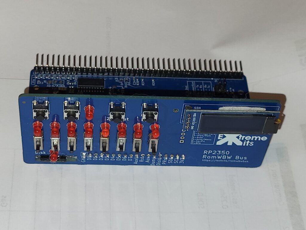
Click here for Construction details for 90 degree front panel
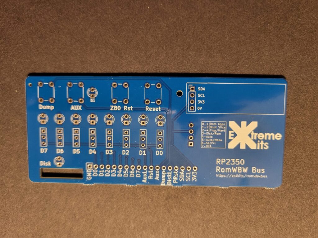
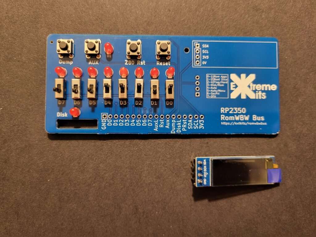
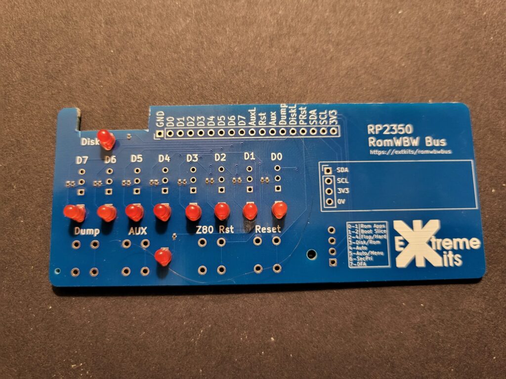
Take the front panel PCB, and carefully break it free of the other panel, and file off the mouse bites.

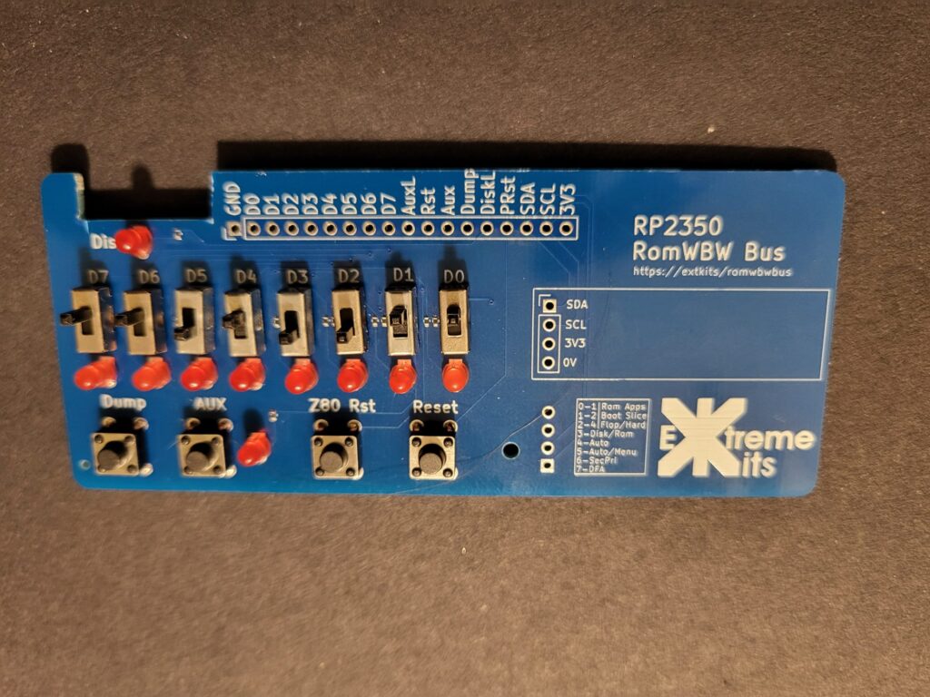
Solder in the 4 push buttons into the position shown
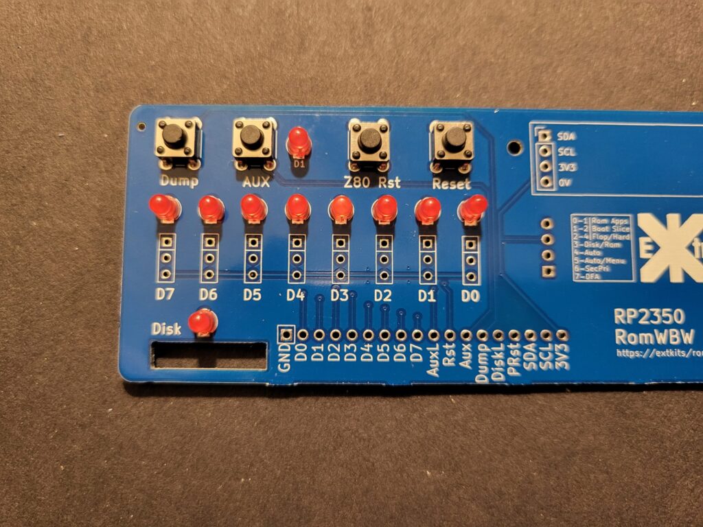
Solder in the 10 LEDs in the position shown, please note that the square pad is for the cathode of the LED, the cathode on the LED is the side with a flat on the body of the LED, or the shorter leg.
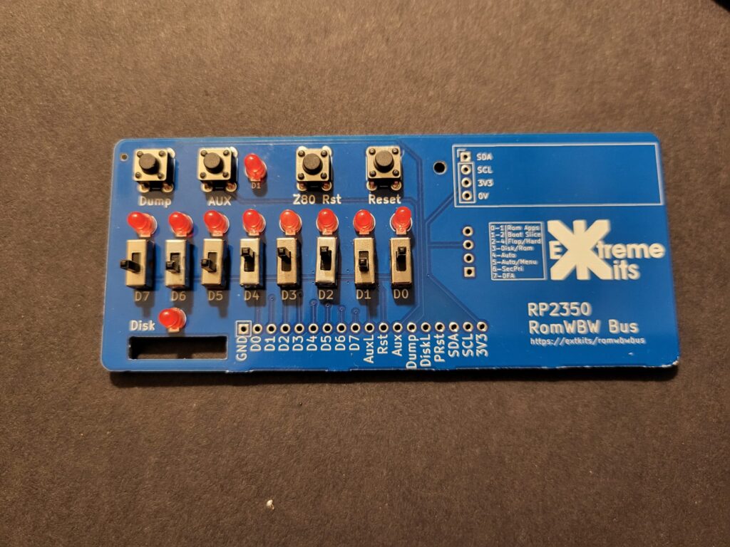
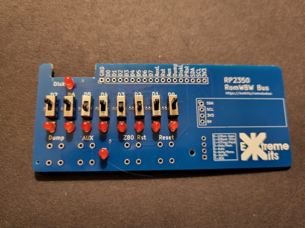
Solder in the 8 switches as shown.
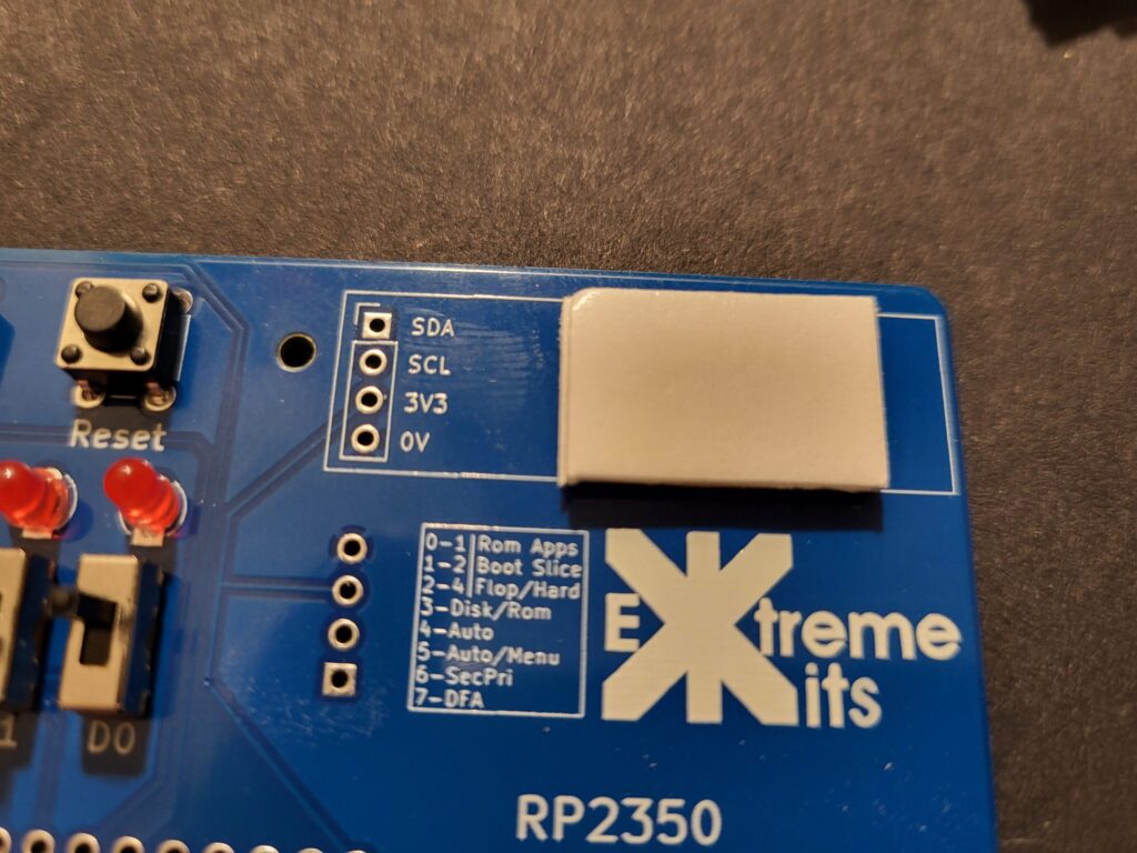
Apply the two sticky pads on top of each other onto the front of the PCB. removing all of the protective backing paper.
Solder in the display and seat on to the sticky pads.
Solder the Front panel to the PCB with an 18 way 90 degree header.
OR
As a single plug in card for direct connection into an RC2014 bus back plane.
Click here for construction details for flat front panel
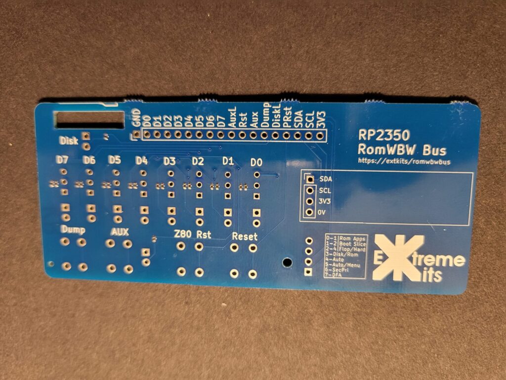
Please note all of the switches, buttons and LEDs are fitted on the reverse of the PCB when building this variant.
Take the front panel PCB, and carefully break it free of the other panel, and file off the mouse bites.
Solder in the 10 LEDs in the position shown, on the reverse side of the PCB, please note that the square pad is for the cathode of the LED, the cathode on the LED is the side with a flat on the body of the LED, or the shorter leg.
Solder in the 8 switches as shown on the reverse side of the PCB.
Solder in the 4 push buttons into the position shown on the reverse side of the PCB

Apply the two sticky pads on top of each other onto the PCB onto the display ident, removing all of the protective backing paper.
Solder in the display in place and seat on to the sticky pads.
You may find the setting PORT:InvSwitches is useful in the rc2040.ini file as the switches are inverted when using the PCB this way around.
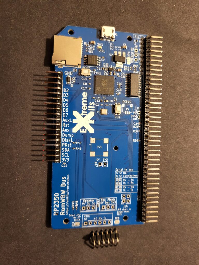
The RC2014 bus connector
So there are 4 options for connecting to the RC2014 bus.
40 way straight connector male
40 way 90 degree connector male
40 way straight connector female
40 way 90 degree connector female
You can use whichever fits your need to connect in to any RC2014 compatible bus backplane. You decide how.
