

Take the PCB and ensure it is clean and free from dirt and grease.

Solder in the
330Rresistor and the
100Rresistor

Solder in the 4 x
100KResistors

Solder in the 1N4007 diode
, ensure the stripe on the diode matches the Stripe on the PCB ident.

Solder in the IC socket, ensure the cut out in the holder matches the PCB ident.

Solder in the 100nF Capacitor and the LED, ensure that the flat on the side of the LED faces the square pad on the PCB.

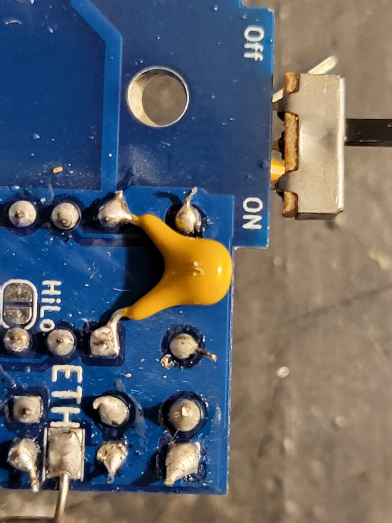
Cut the legs on the switch down to 4mm (the picture shows them uncut), and solder onto the pads on the PCB.

Solder in the Mosfet. The Mosfet may be a number of different types. (not necessarily 30N06L).
If the Mosfet has a metal heat sink, ensure that it is not touching the switch contacts.

Solder in the 100uF capacitor, ensuring the stripe on the capacitor, matches the white half of the ident on the PCB
Solder in the PCB power connector, ensure the connector is the way around shown on the PCB and photo.

Solder in the 6 high voltage diodes
Ensure that the blue markings or the 00000 markings, are towards the square pad (k) on the PCB.
Please note: these diodes have a reverse voltage drop of over 40V they will not measure anything on a standard meter or with a diode test.
Some variants of this diode are slightly longer than the PCB holes. In this case you will have to solder the diodes in at a slight angle.

Solder in the 6 high voltage 100nF capacitors

Take the transformer and separate the 6 wires
Note: do not remove the transparent tape from around the transformer, it holds the core together.

Cut off the two thinner wires to 3mm long and fold them flat against the insulation around the transformer.

Cut the two thick enamelled wires to 7mm, and scrape off the enamel of the end 4mm with a sharp knife. This needs to be clean as the enamel is not soldering iron removable.

Trim the two high voltage leads from the transformer.
The bottom (PCB) lead needs to be trimmed to 20mm, with 8mm of insulation removed.
The upper lead needs to be 30mm long with 8mm of insulation removed .

Solder in the transformer with the two enamelled wires

If the enamelled wires look like this after soldering you have not cleaned off enough enamel. Remove the transformer and re clean the wires.

Solder in the bottom and top HV wires as shown.

Cut a 20mm length of tinned wire and solder it to the ETH pad on the bottom of the PCB.

Wind 120mm of tinned wire around a screwdriver, knitting needle, or similar rod 3-5mm in diameter to form a spring.

Solder the spring onto the HT pad on the PCB and stretch it out to 35mm.
I have added an extra capacitor 10uF for stability, This should be soldered across pin 1 and 8 of the IC on the underside of the PCB as shown.
On future PCB releases, this will be included on the PCB and replace the 100nF capacitor.
That is the Electronics built.

Insert the IC into the socket, ensuring the cut out at the end of the IC matches the cut out in the socket.
Do not power up the PCB, even with the switch in the off position, without the IC in place, This can damage the MOSFET.
If you test the PCB out of the case, ensure that the earth wire is earthed, and there is noting near the HV end or PCB. Avoid touching the PCB or components when it it powered on.
Warning:
Although the voltages produced by product are safe for humans, this is not true for any other electronic device. IT MUST NOT BE USED WITHIN 300mm OF ANY ELECTRONIC EQUIPMENT. Also be aware whilst using the device you may pick up electrostatic charge, do not operate any electronics whilst using the device. You are a conductor.
Do not use if you have a pacemaker, cochlear implant or and electronic controlled medical device.
Does contain small parts and is therefore not suitable for small children.
This device is not intended to be run from an external power supply, and it is UNSAFE to do so.
This device should not be used to charge capacitors or external electrical storage devices.
