
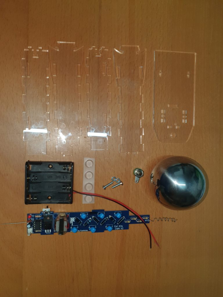
Take the hardware parts and the completed Electronics. (Electronic instructions here)
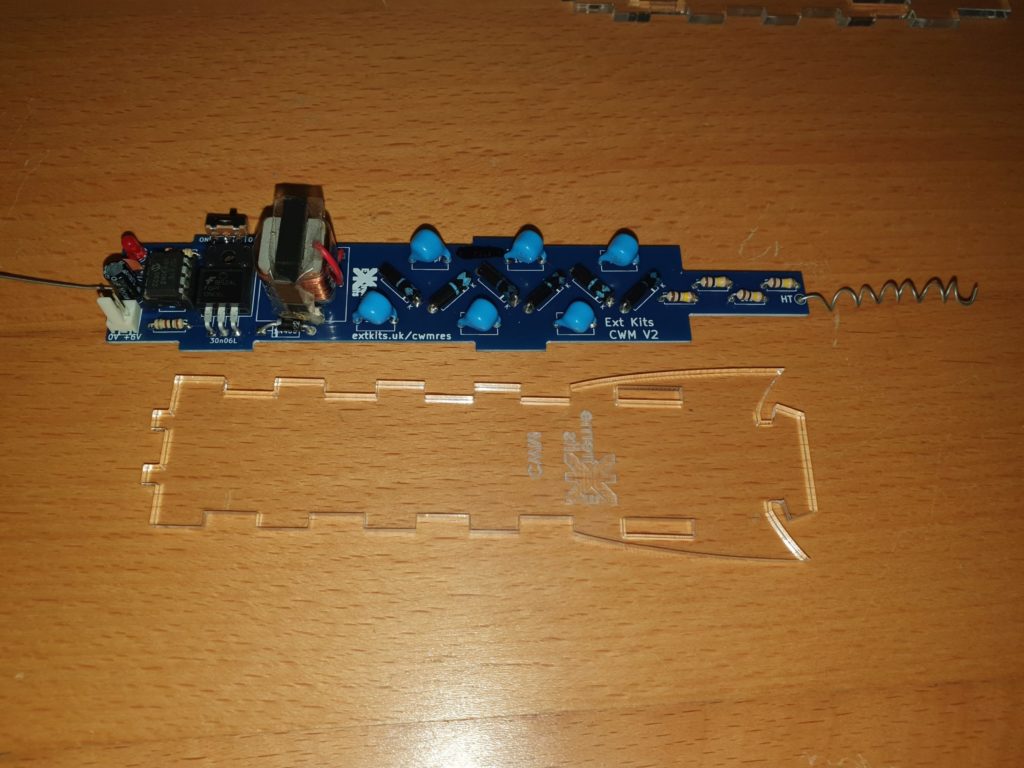
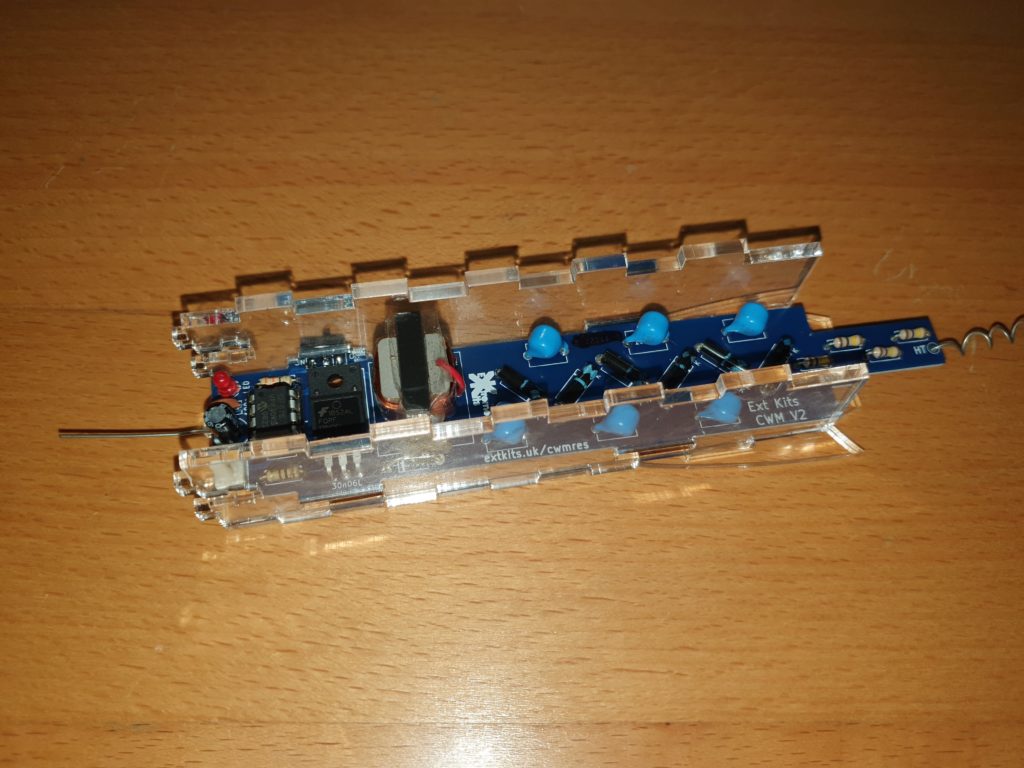
Take the front piece of acrylic (engraving downwards) and the completed electronics.
place the PCB on top of the front piece of acrylic.
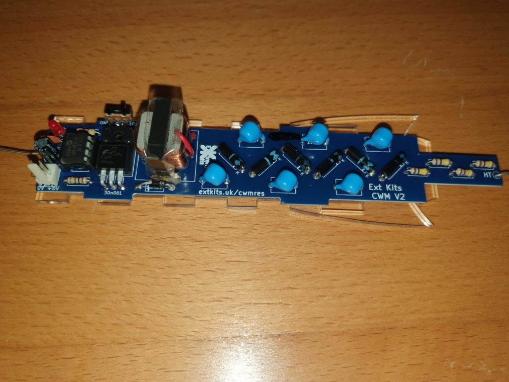
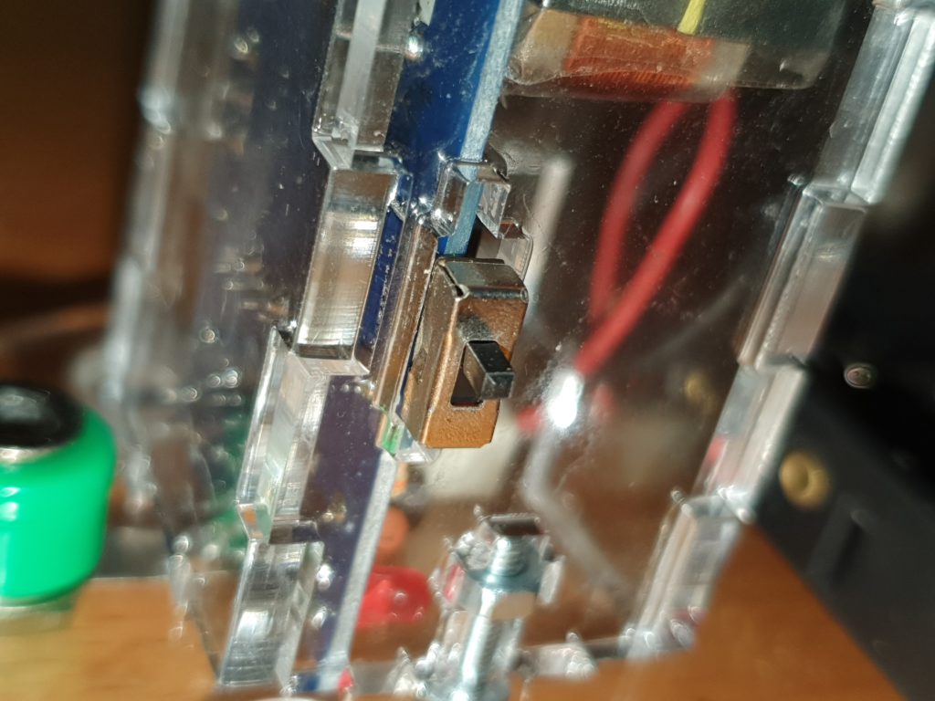
Take the left side acrylic piece (with the larger slot for the switch) and slot into the front acrylic piece and push the PCB switch and tabs into the slots on the side piece.
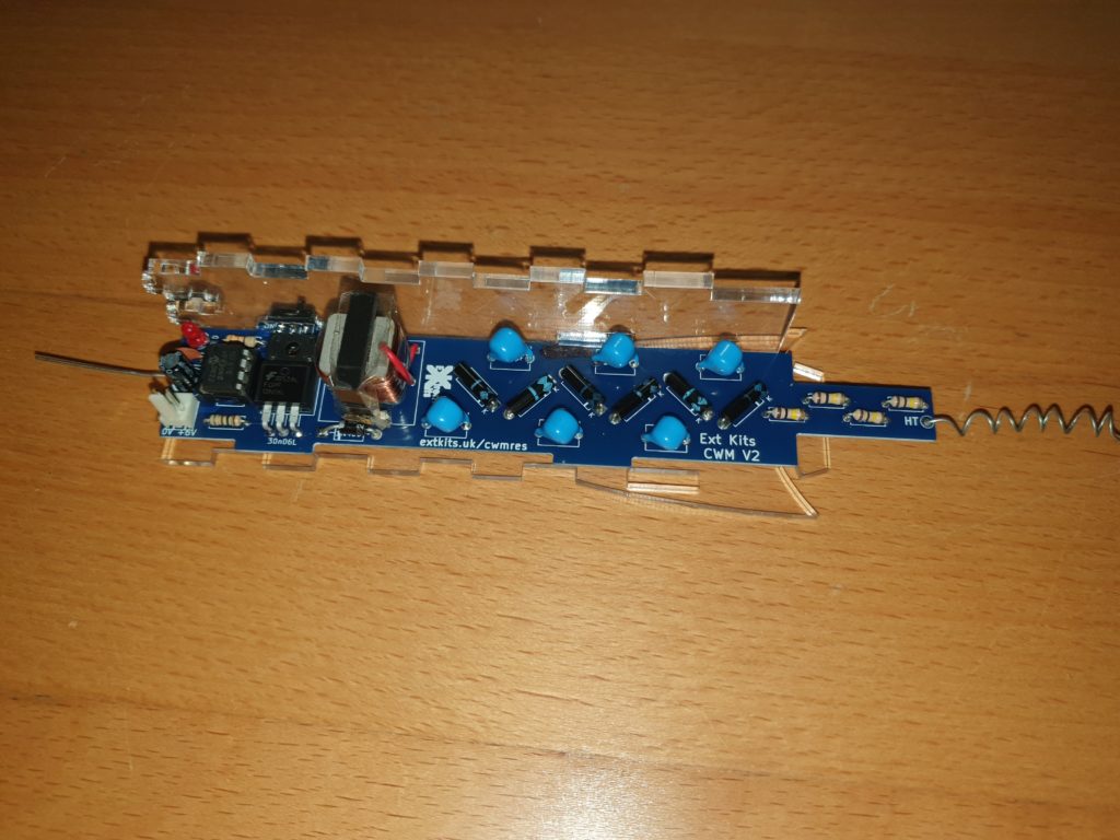
Take the Right side piece and seat the PCB tabs into the right side piece and slot the right side piece into the front piece slots.
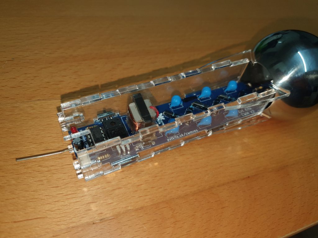
Take the Top Ball and hook the top of the front piece into its hole
Take the back piece, at an angle, and hook the top into and under the hole.
Seat the back piece onto the left and right acrylic pieces tabs.
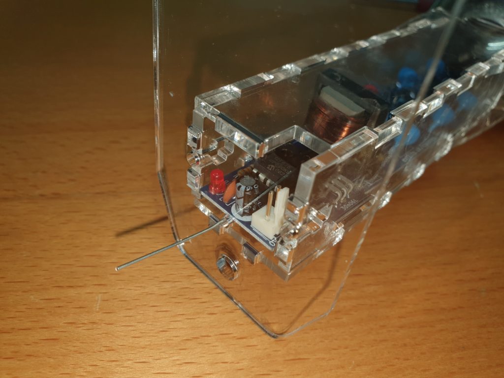
Push on the bottom plate onto the tabs of the other pieces, ensuring that the earth wire exits through the small round hole.
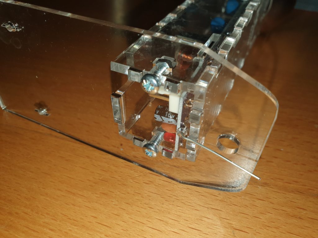
Secure with 2 x 10mm M3 nuts and bolts.
It helps to use a piece of blutack, or a small magnet to hold the nuts in place whilst you are screwing in the bolts.
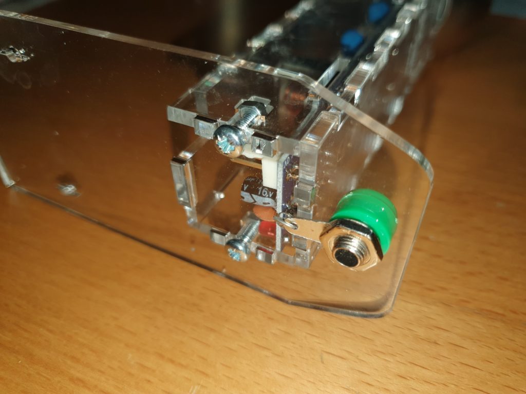
Pass the earth wire through the small hole in the 4mm earth terminal lug.
Screw in the 4mm earth terminal and tighten.
Fold over the earth wire and cut to length
When you have proved everything works, you could solder this connection.
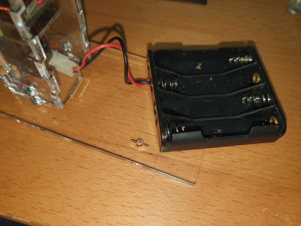
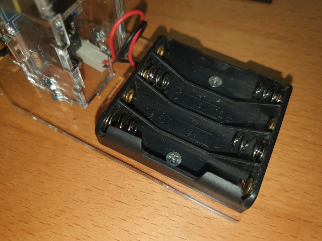
Connect the empty battery box to the PCB
Screw the battery box to the bottom plate with 2 x 4mm chamfered m3 bolts.
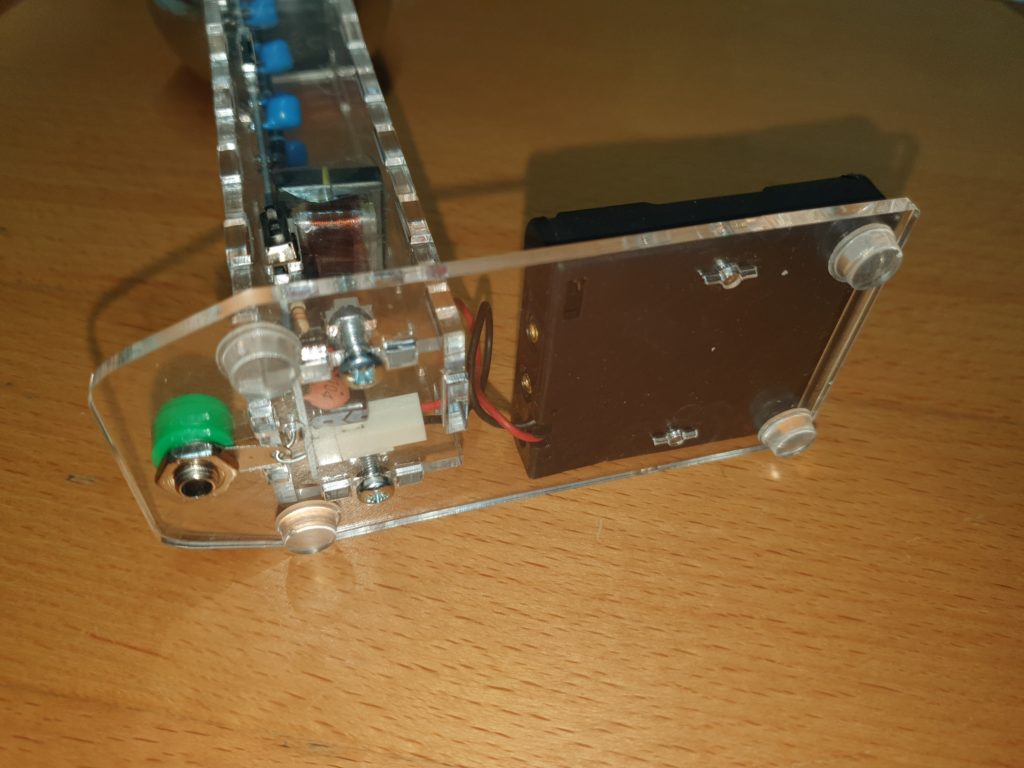
Stick on the feet where shown.
Ensure the switch in is the UP (Off) position
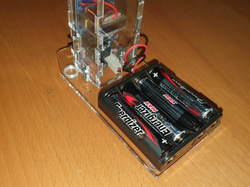
Before inserting the batteries. Ensure they are in the correct way around according to the ident in the battery box.
Congratulations you have built your Cockcroft Walton Multiplier.
