
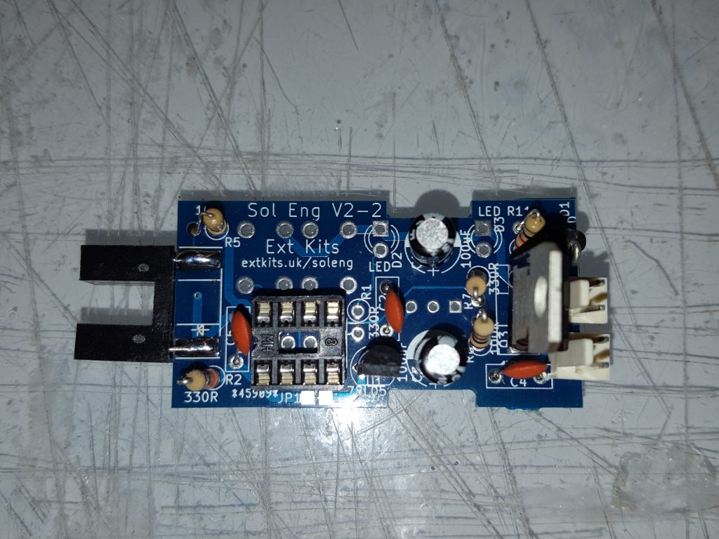
The Solenoid Engine PCB Component side
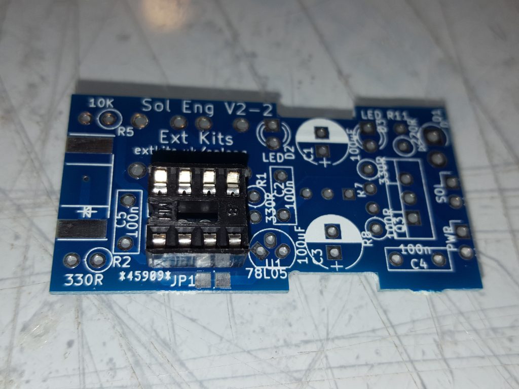
Insert and solder in the IC holder, Make sure that the Socket D cut out follows the ident on the PCB
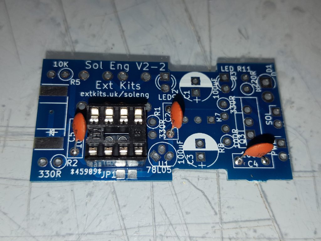
Add in the three 100nF capacitors
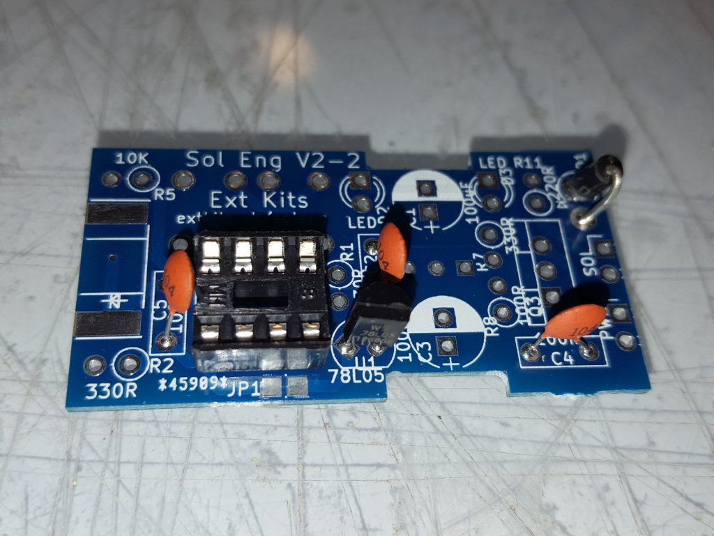
Solder in the 1n4007 diode,ensure the white ring on one end of the diode goes into the hole with the square pad. Solder in the 5v regulator make sure the D of the regulator matches the D on the PCB ident.
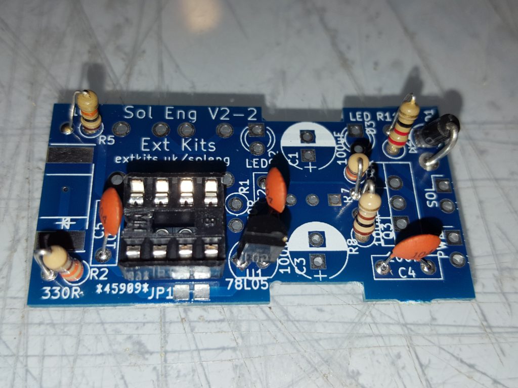
Solder in the resistors. 1 x 220 ohm (Red Red Brown), 1 x 100 ohm (Brown Black Brown), 3 x 330 ohm (Orange Orange Brown), 1 x 10K (Brown Black Orange)
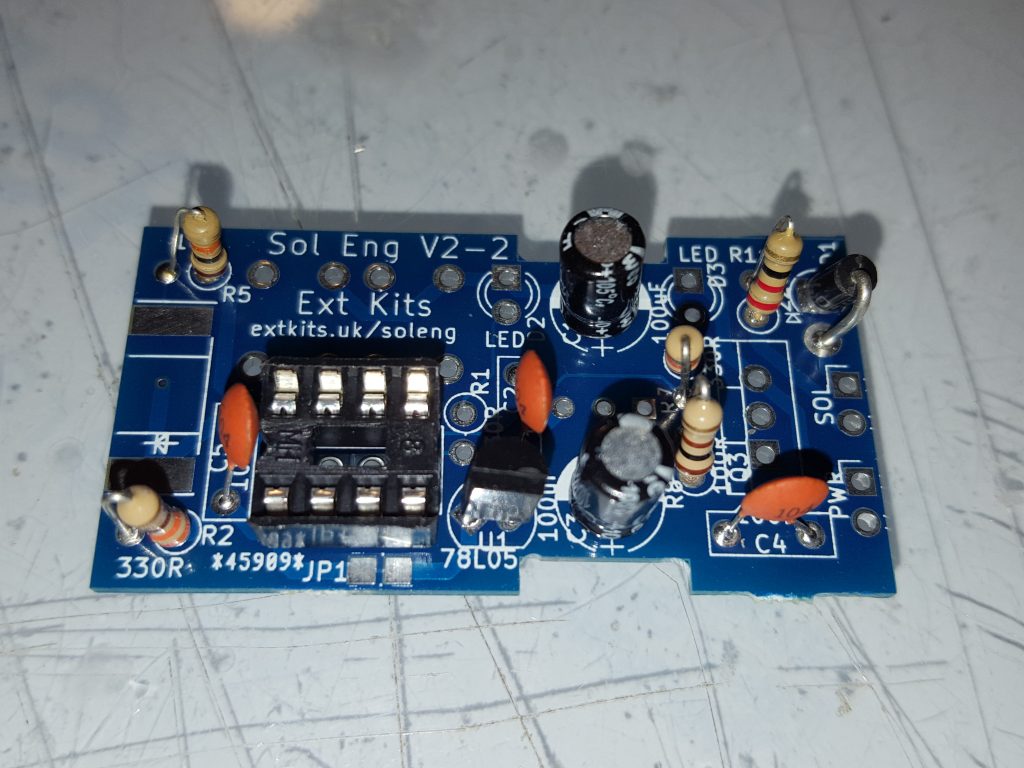
Insert the two capacitors,match the white stripe to the white semi-circle on the ident.
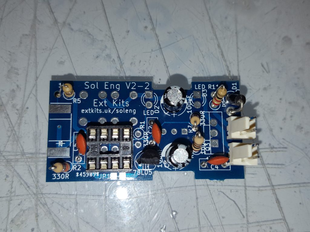
Solder in the two 2 way connectors, ensure the catch on each connector is as shown above.
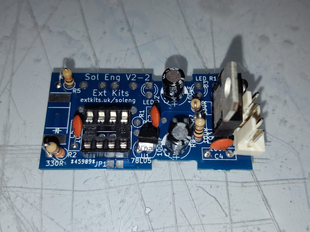
Solder in the power transistor the metal tag should match the white square on the PCB ident.
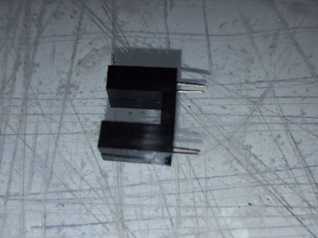
Trim the legs on the Slotted Opto to 5mm long, Slightly bend them so they nearly meet
With the Diode symbol on the Slotted opto matching the one on the ident, Slide the PCB between the pins, ensure the Opto sits flush and straight to the PCB, solder the pins on both top and bottom,
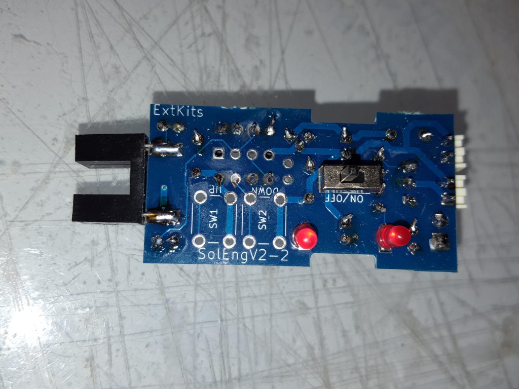
Flip over the PCB and solder the LED’s as shown, make sure the anode (long leg) of the LED goes to the square pad on the PCB,
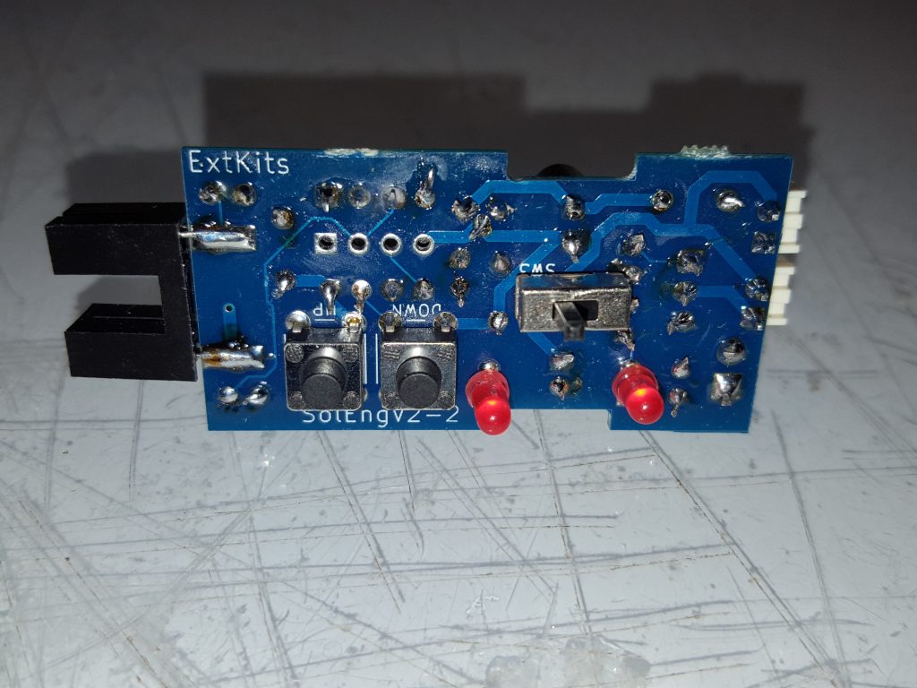
Insert the switch and the two push buttons and solder in.
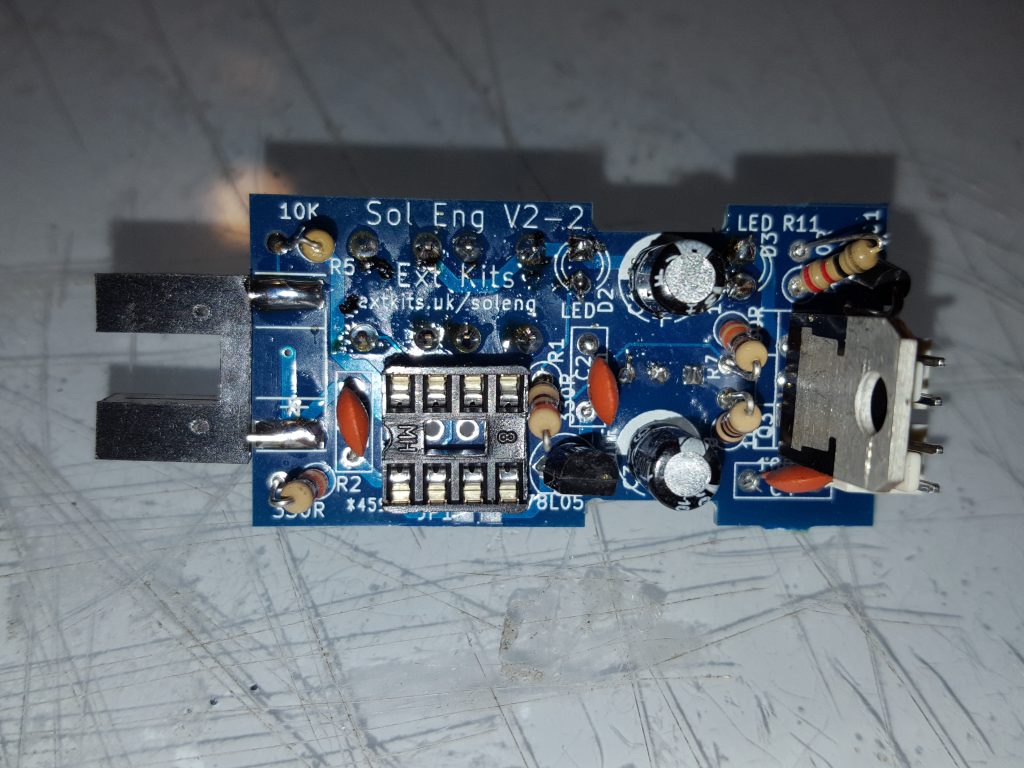
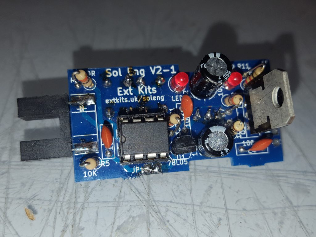
The completed board.
Insert the Microprocessor into the socket, make sure the D cutout on the Socket matches the cut out on the microprocessor.

