
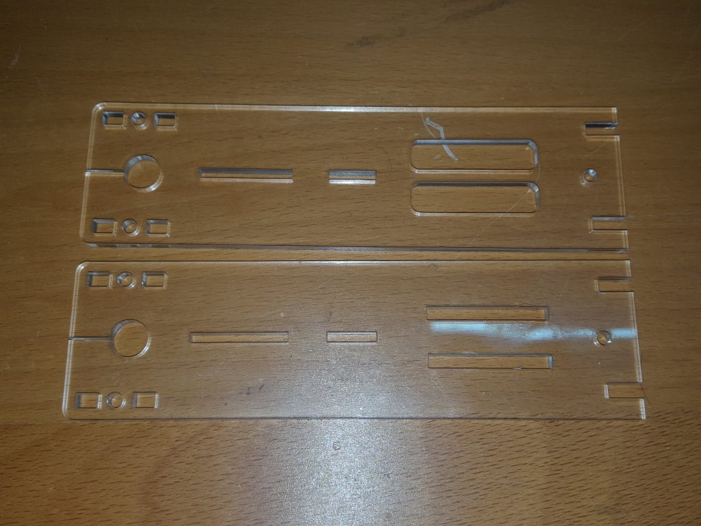
 Take the two side peices
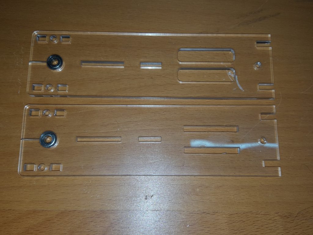 and insert the 4x4x9mm ball bearing races in to the two holes as shown, A screwdriver can be used in the slot to carefully open up the hole if needed.
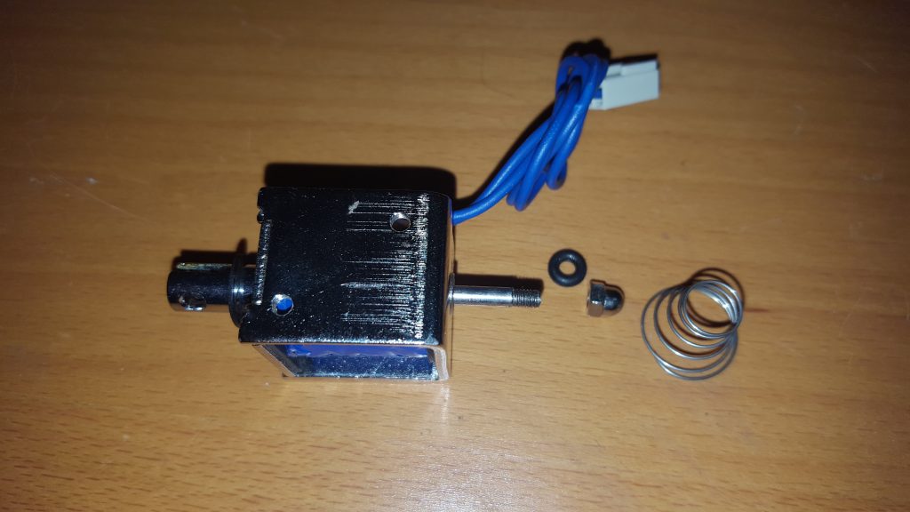 Prepare the solenoids by unscrewing the domed nut and removing the rubber ring and spring.
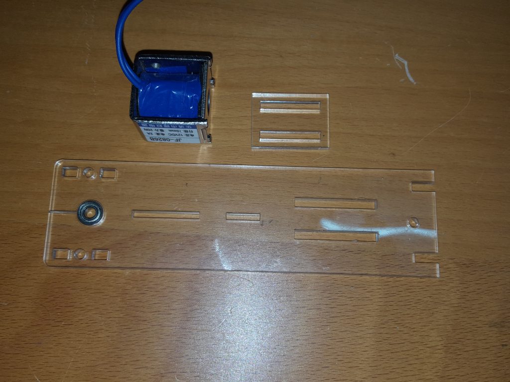 Take the solenoid coil, solenoid mounting plate and the side with the smallest mounting slots
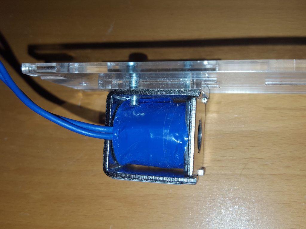 Using 2 x 10mm x m3 bolts screw in the solenoid through the mounting plate with the large hole of the solenoid pointing towards the ball bearing
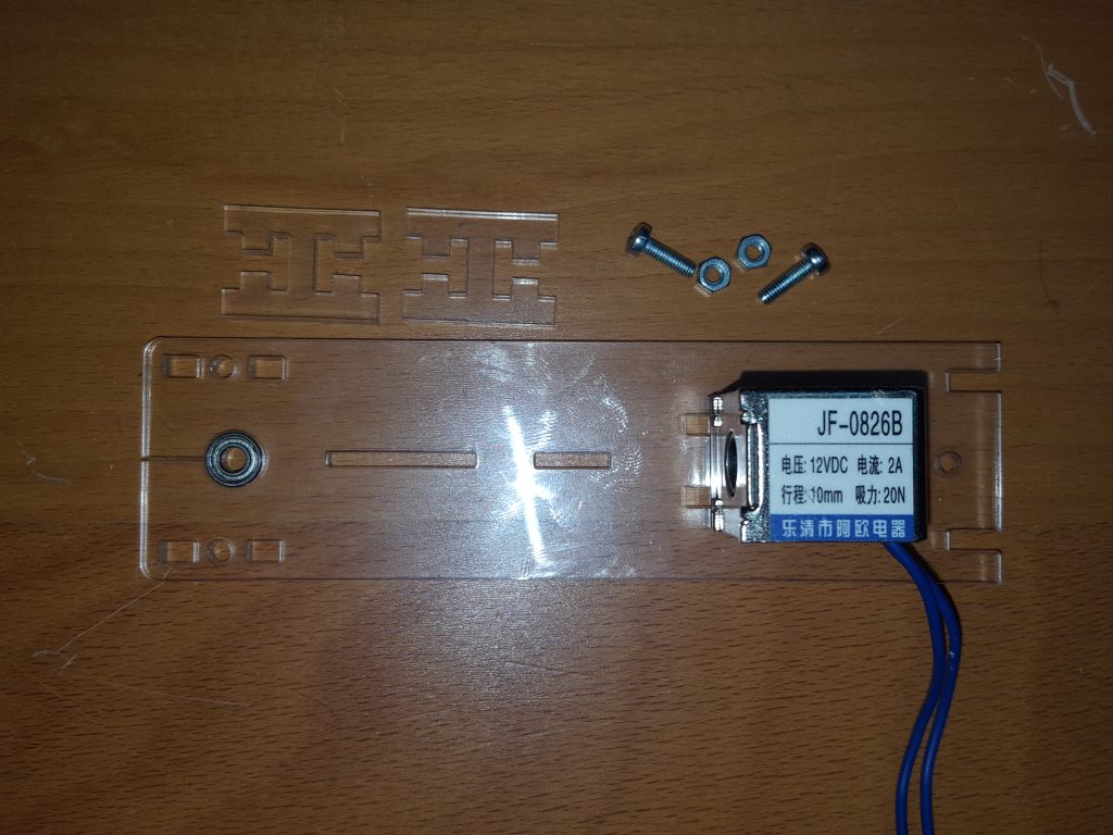 Take the two top spacers 2 x 10mm x m3 bolts and the completed solenoid plate
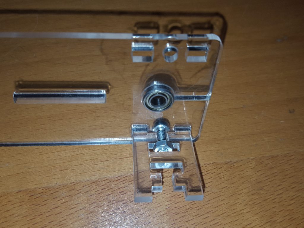 Screw in the two mounting plates using the nuts and bolts.
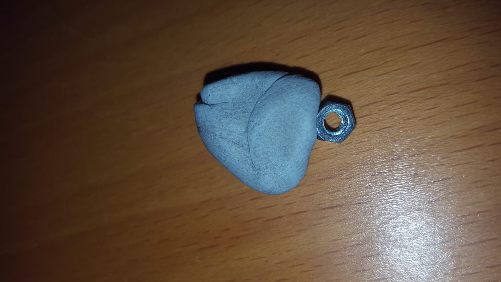 A tip here is to use a piece of blue tack to hold the nut until the bolt has started into the nuts thread
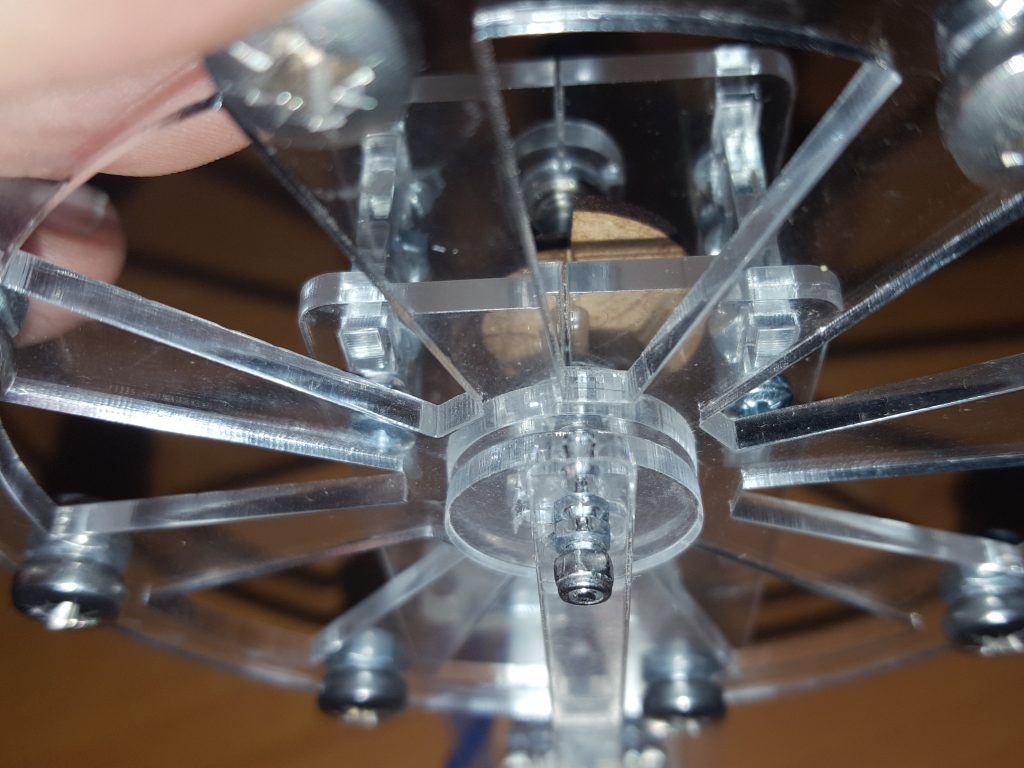
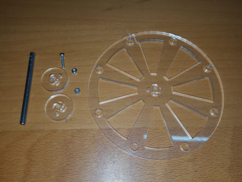 Take the Flywheel, the axle, the two friction plates, a m2 x 16mm bolt and two m2 nuts
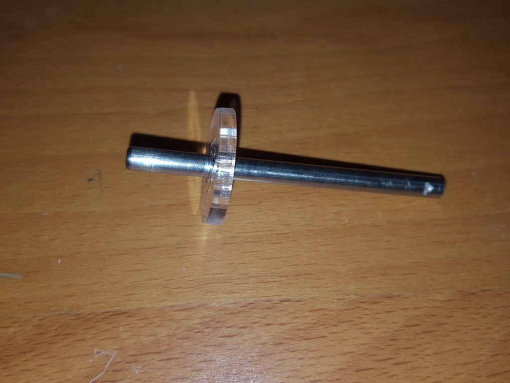 First push one of the friction plates onto the axle, leaving enough space for the flywheel and the second friction plate.
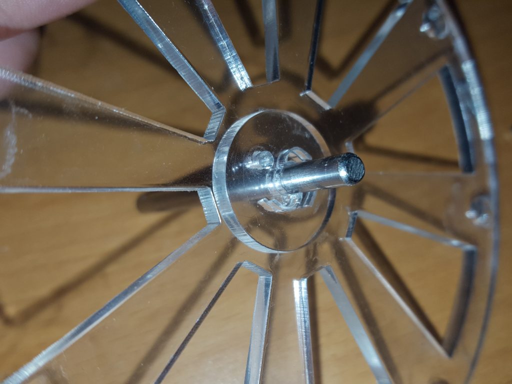 Push on the flywheel, and align the m2 holes.
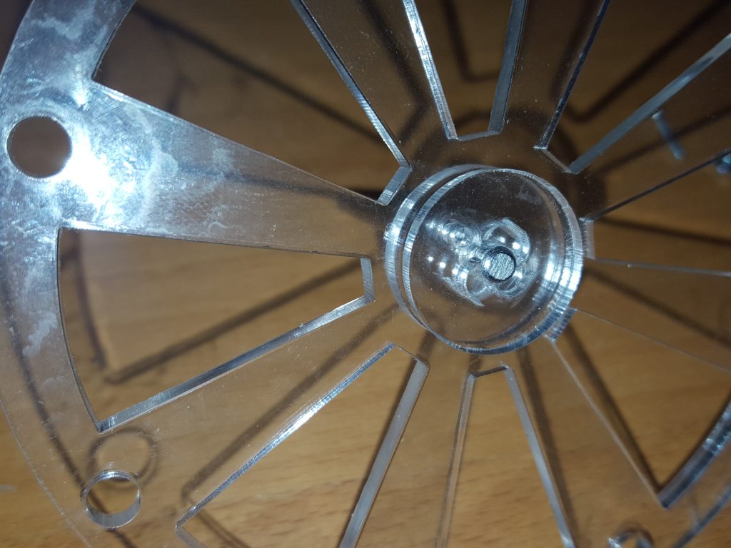 Push on the second friction plate, and again align the m2 holes
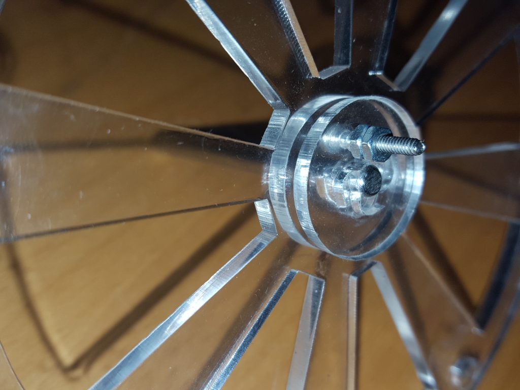 Push the assembly right to the end of the axle, and insert in the m2 x 16mm bolt through the flywheel and the two friction plates. Secure tightly with two m2 nuts.
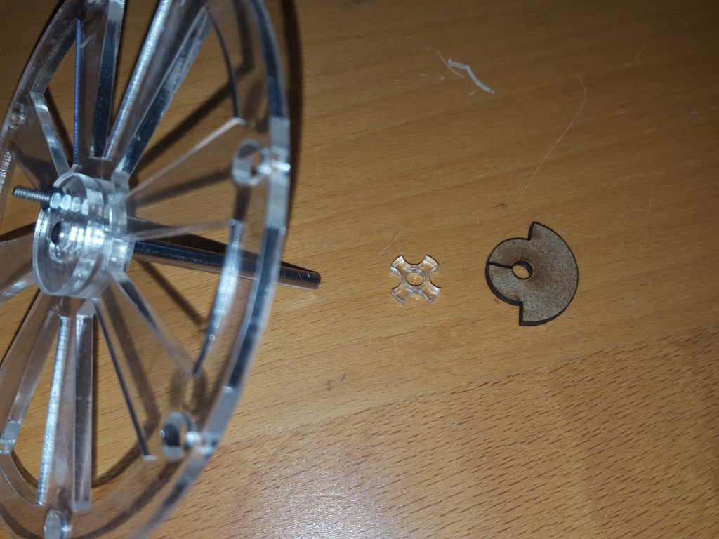 Take the star spacer and the cam.
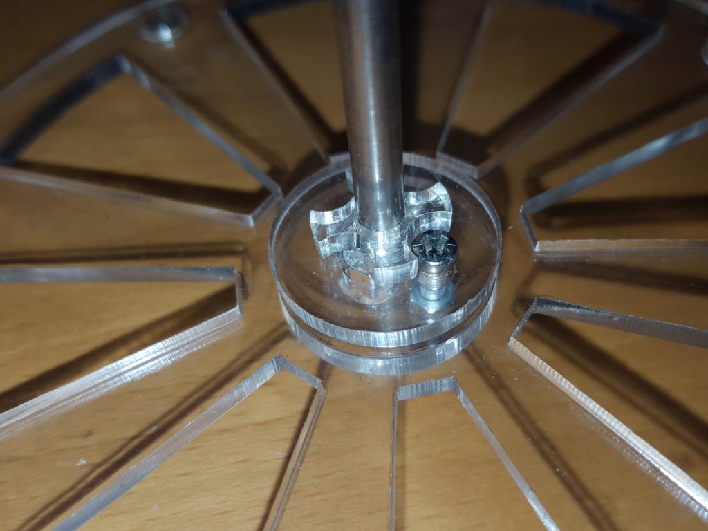 place the star spacer on the axle behind the flywheel assembly
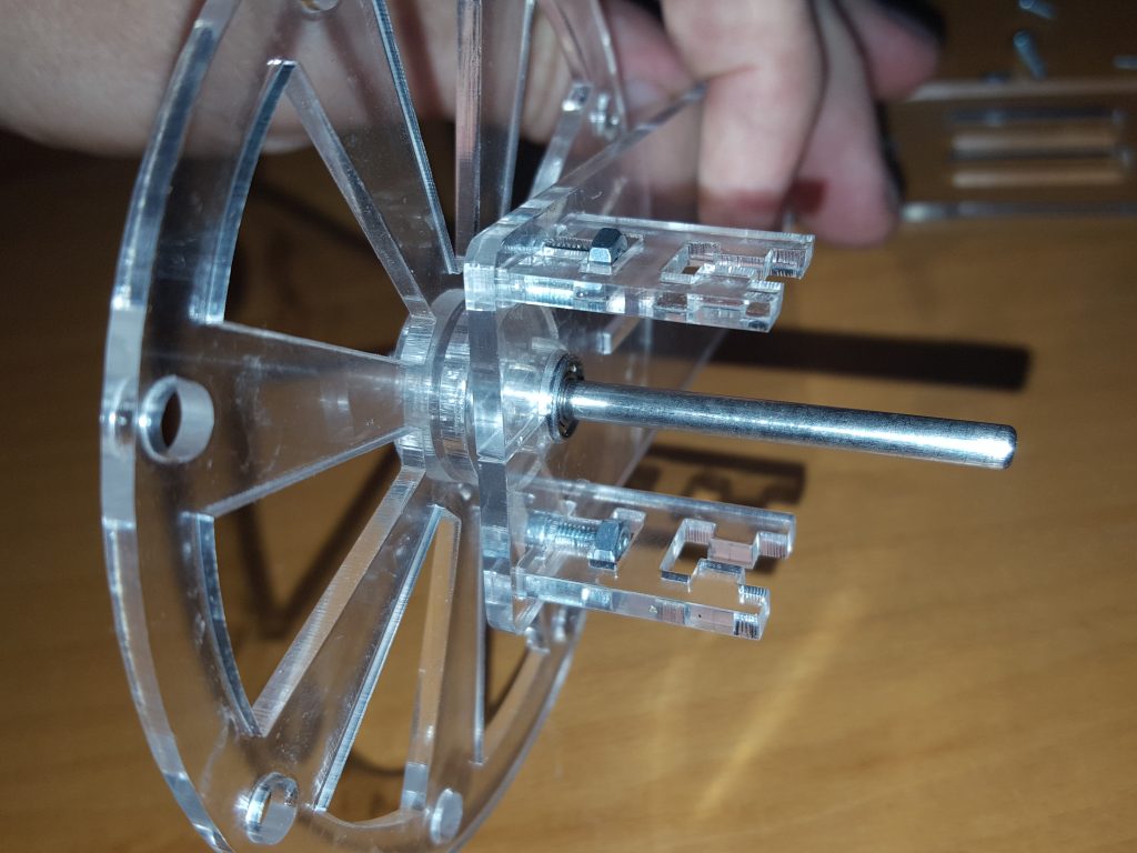 Push the axle through the bearing on the solenoid plate.
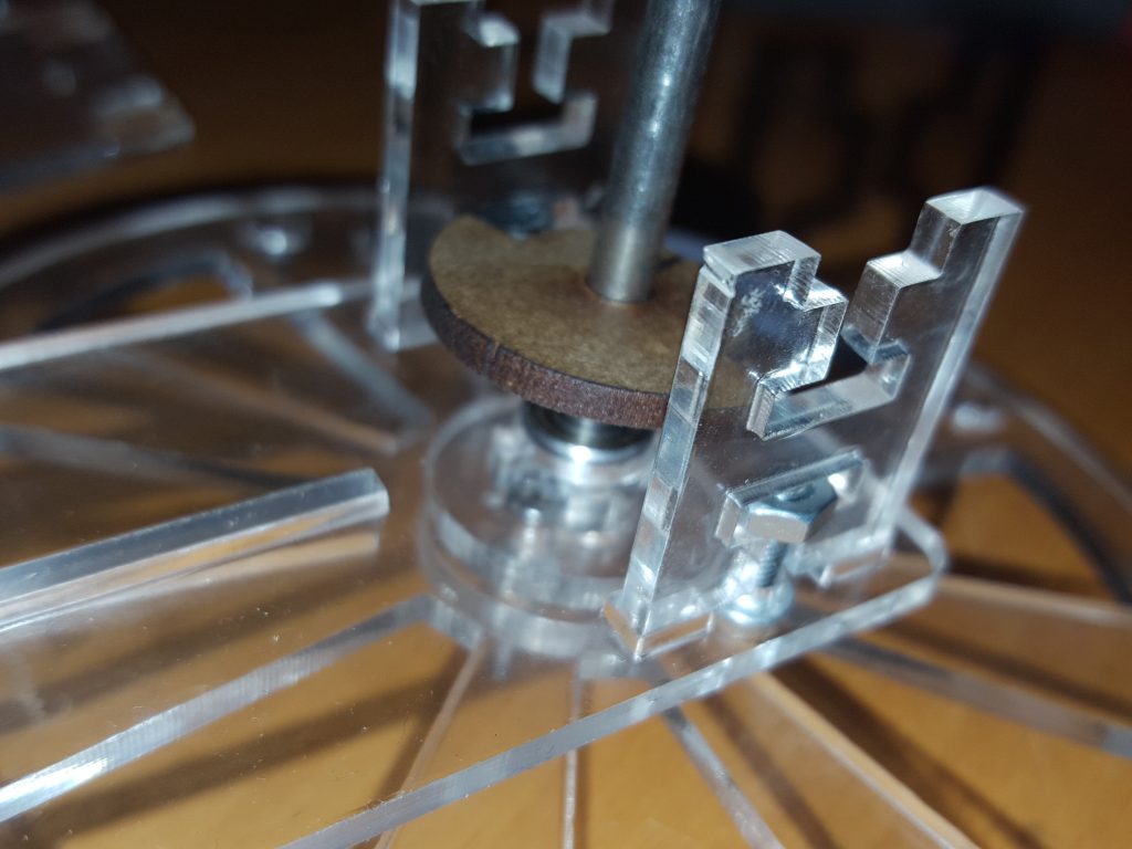 Push the cam on to the axle, until it sits in the middle of the spacer plates.
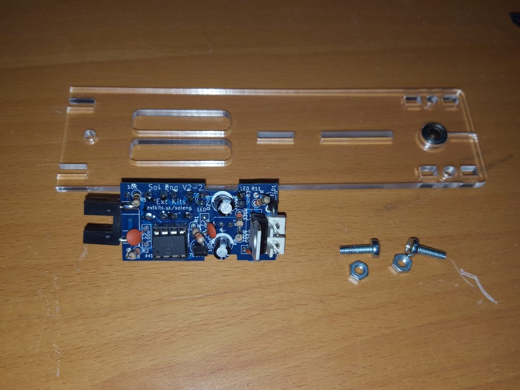 Take the remaining side 2 x m3 x 10mm bolts, 2 x m3 nuts and the completed electronics PCB.
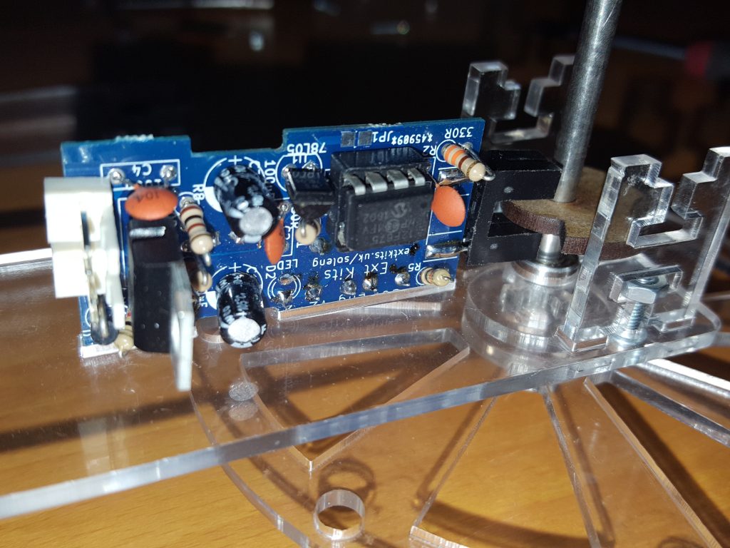 Push the electronics into the slots in the solenoid side plate. The slotted opto should fit either side of the cam
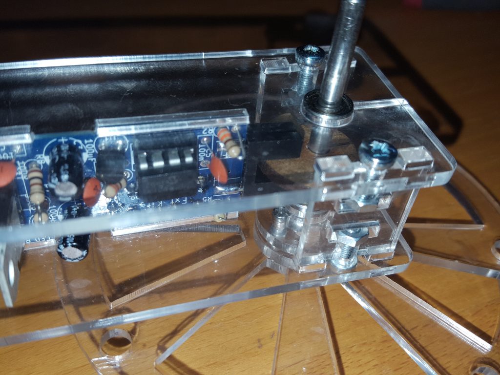 Fit the axlethrough the bearing on the second slide plate and move the plate down so it captures the electronics and the spacers. Screw the side plate on to the spacers with 2 x m3 x 10mm bolts and 2 x m3 nuts.
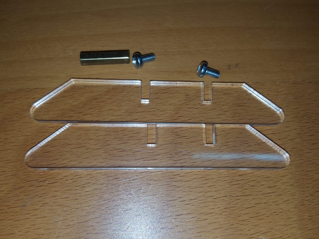 Take the 2 x m3 x8 bolts and the m3 x 20mm threaded spacer.
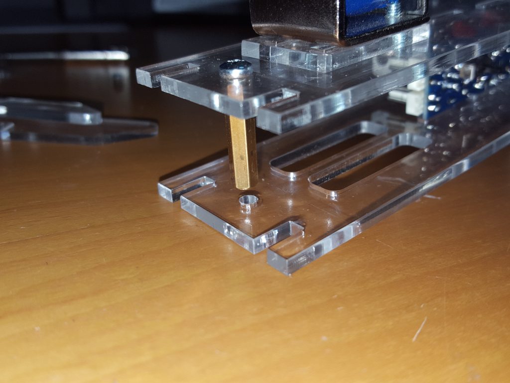 Attach the threaded spacer to one side peice with an M3 x 6mm bolt
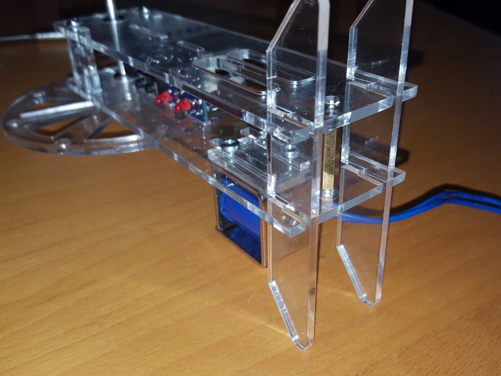 Place the two feet into the slots in the side pieces, ensuring that the longer sides of the feet is on the solenoid side of the assembly. Using the second m3 bolt screw into the threaded spacer to retain the feet.
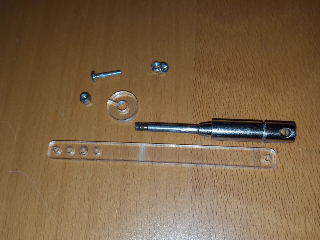 Take the solenoid armature, the con-rod the back retainer a m2 x 10mm bolt and and 2x m2 nylock nuts
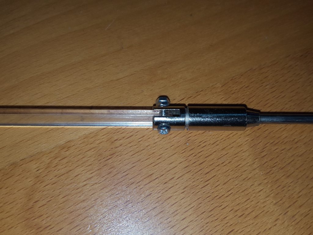 Using the m2 x 10 mm bolt attache the con rod to the middle of the armature and secure with an m2 nylock nut. Tighten so there is a small amount of slack, but the con-rod can still move freely.
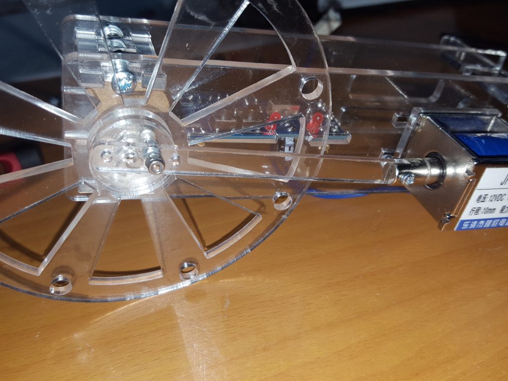 Insert the armature into the solenoid and attach the con-rod to the m2 bolt on the flywheel, secure with a nylock nut. Tighten so there is a small amount of slack, but the con-rod can still move freely.
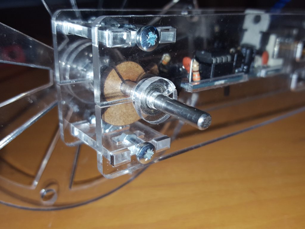 Slide the back retainer onto the axle to stop any sideways movement of the axle, whilst allowing it to turn freely,
Setting the Timing Cam
 Ensure the timing cam is central to the slotted-opto so it will not catch as the flywheel moves. Place the flywheel so that the con-rod is at its highest position.
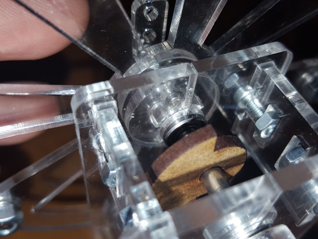 Slide the cam around so the wood just starts to enter the Slotted-opto when the con-rod is at its highest position.
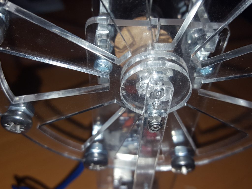 The Solenoid needs to be set so that at the top position the armature isn’t pulled out of the solenoid body, and at the bottom position the armature doesn’t bottom out
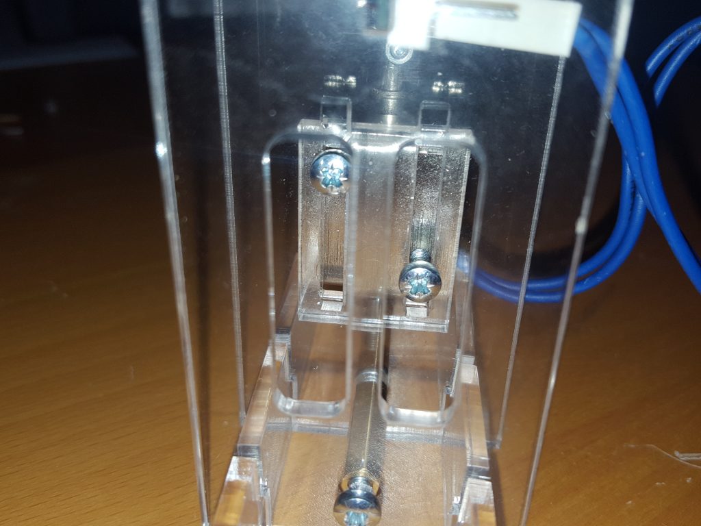 This can be adjusted by setting the hole used for the flywheel bolt at the top of the con-rod. Or by sliding the solenoid up and down using the screws and slots at the back of the solenoid.