
Connecting an RC2014 with Digital I/o Board To the Ext Kits Solenoid engine with a Micro:Bit/Raspberry Pi interface
You will need a RC2014 with a Digital I/O board for this.
and a
On the RC2014 Digital I/O you need to add connectors for (at minimum) IN 0 and Out 0
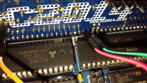
I added a row of 2.54 header strip on the pins 11-18 of the 74ls245 giving me access to the 8 input port bits
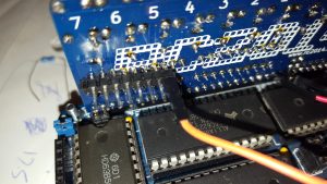
and a row of 5.08 (I took every other pin out of a 2.54 header) header on the bottom of the row of resistors feeding the LEDs to give me access to the 8 output bits
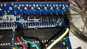
I also added a 2 pin header on pins 17 & 18 of the mother board connector for easy access to GND and +5V
I then wired from the Digital I/O board
In0 to EYE
Out0 to SOL
GND to 0V
+5 to 3.3V (yes really)
on to the Solenoid engine board.
To increase the input impedance of the In0, I removed the associated pull down resistor.
Running this board at 5v is fine, but it does make the sensor rather sensitive. I suggest changing r2 for a 470R on the Solenoid engine board to compensate.
Warning in the code samples below there is no way of ensuring that the program doesn’t stop with the solenoid ON. If this happens the Solenoid and Transistor may get quite hot.
Please note. To run this on V1 Engines you need to invert the Input
Sample Code
Flat out – Test code
10 I=INP(0)
15 PRINT INP(0)
20 IF I=0 THEN OUT 0,0
30 IF I=1 THEN OUT 0,1
40 GOTO 10
Speed Control
10 REM Set speed by the S variable
20 S=50
30 C=0
40 H=0
60 C=C+1
70 IF C<5000 THEN GOTO 100
80 PRINT "Engine has stopped"
90 C=2500
100 P=INP(0)
110 E=0
120 O=1
130 IF P<>0 THEN GOTO 200
140 IF C<S THEN GOTO 200
150 O=0
160 IF H<>O THEN PRINT C
200 IF O=0 AND H<>O AND C>S THEN C=0
210 H=O
220 REM
230 OUT 0,O
240 GOTO 60
Variable S controls the speed of the engine s=2 Fast – S=200 Slow
Sorry, used ‘O’ for an output variable, seamed a good idea at the time, but in some terminal emulators beware of O, o and 0 🙂