
Coming soon…
Most of the details are here, and Ill post more as I can, I’m aware of images and details missing.
If you care stuck with anything, contact me and Ill sort.
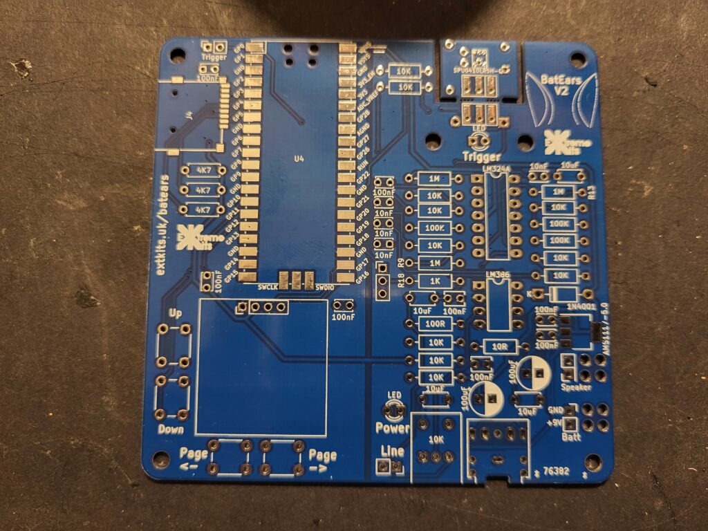
Ensure your Bat Ears PCB is clean and dry

Carefully solder in the SD card holder with a fine tipped soldering iron. Some liquid flux can make this easier.

Solder on the PI Pico flat to the PCB with the USB connector to the outside of the PCB.
Ensure all of the pads a re square to the pads on the PCB before soldering.

Solder the header on to the display with the longer pins facing downwards.
Place the display on to the PCB and solder in place. Cut off the excess pin lengths on the under side of the PCB

Solder in the 4 Buttons to the PCB

Insert 3 x
4k7next to the SD card.
At this point apply a USB connection to the PICO and Ensure the Bat Ears logo is displayed on the screen.

Insert 12 x
10Kin the places shown, also solder a 10K into the resistor marked R13.

Insert 2 x
1Mresistors as shown. (not R13 should have a 10K resistor in place, not as shown)

insert 3 x
100Kresistors into the places shown.

Insert the switch (or link) into the centre of the PCB, and add the
1n4007 ordiode as shown, ensuring that the white stripe faces towards the K on the PCB ident.
Also solder in the 2x
1KResistors (on is on the microphone PCB)

Solder in the two IC’s ensuring that the cut out matches the cut out on the PCB.
Add in the 5
[ccode 10uF]Capacitors. (there is also on on the microphone PCB
Solder in the 4
[ccode 10nF]Solder in the 8
[ccode 100nF]Capacitors (one is on the microphone PCB)
and the two
[ccode 100uF]Capacitors
Solder in the regulator.
and solder in the two LED’s The Green one for power and the red one for signal detect.
!led!