
Tools Required
- Small posi-drv (+) screwdriver
- File (not essential)
- Soldering iron, solder
- Small Wire Cutters
- micro USB lead
- 5v USB power supply 1A or more
Please note: there is a revision to this PCB, version 1A, with additional components and some component positions moved.
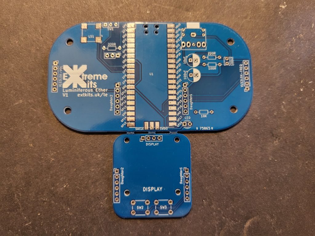
Take the PCB and break off the display daughter board PCB from the main PCB
If you like you can file down the mouse bites that are left to neaten the PCB edge
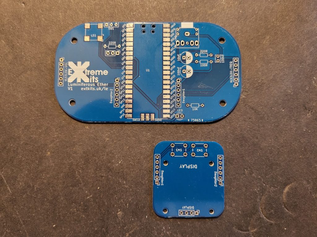
Save the Display PCB for later.
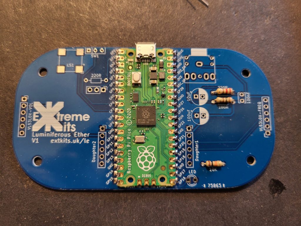
Ensure the PCB’s are clean and undamaged.
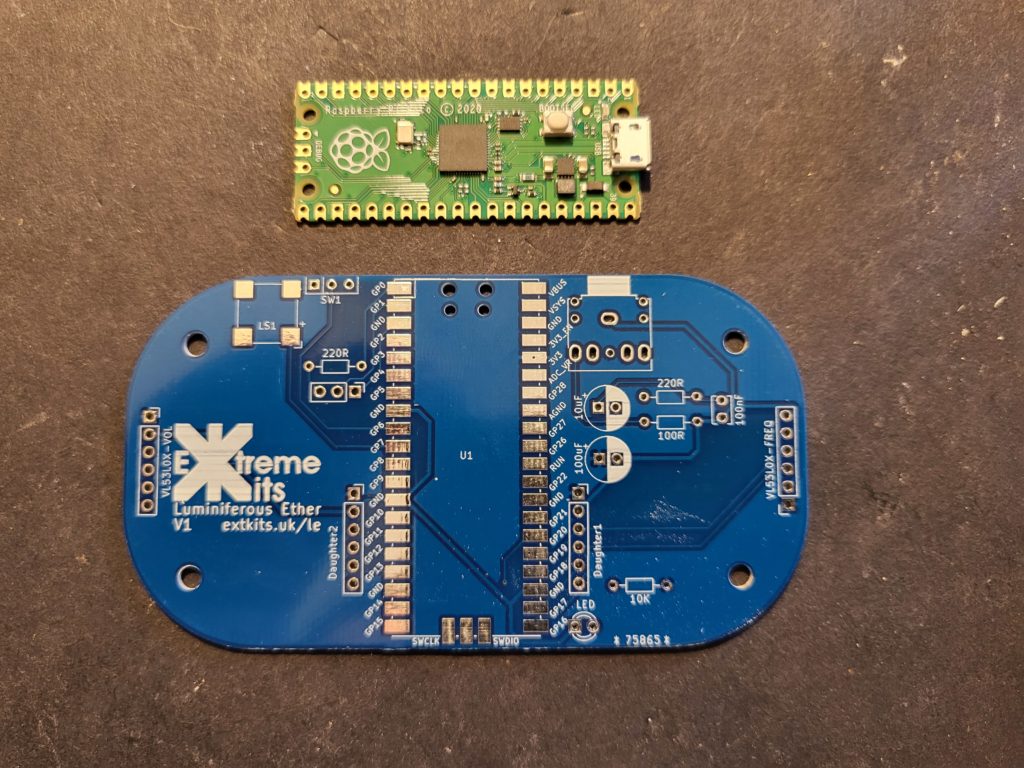
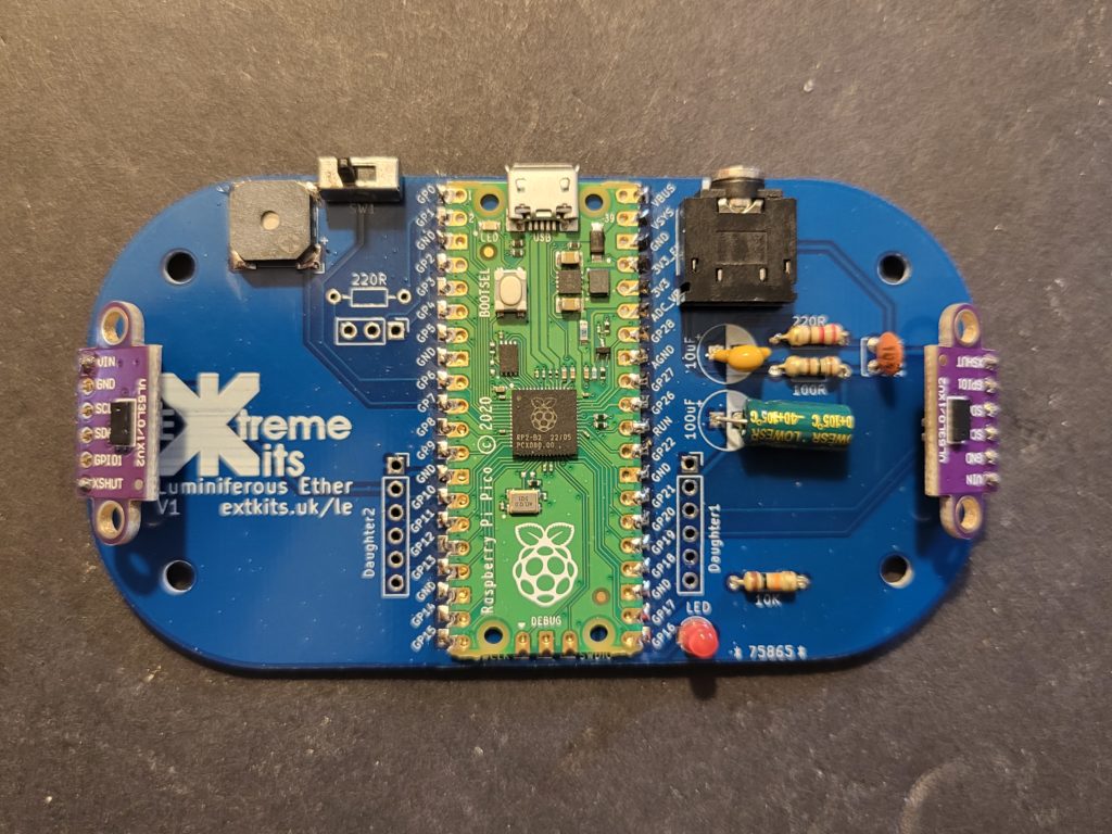
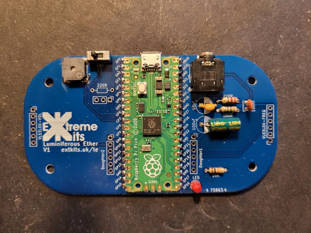
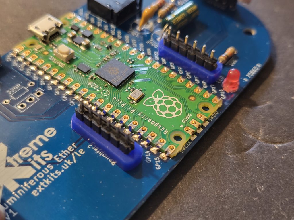
Taking the Pi Pico, Orientate the Pi Pico so the USB connector is towards the top of the PCB, and the three pads for the debug header line up with the pads on the PCB
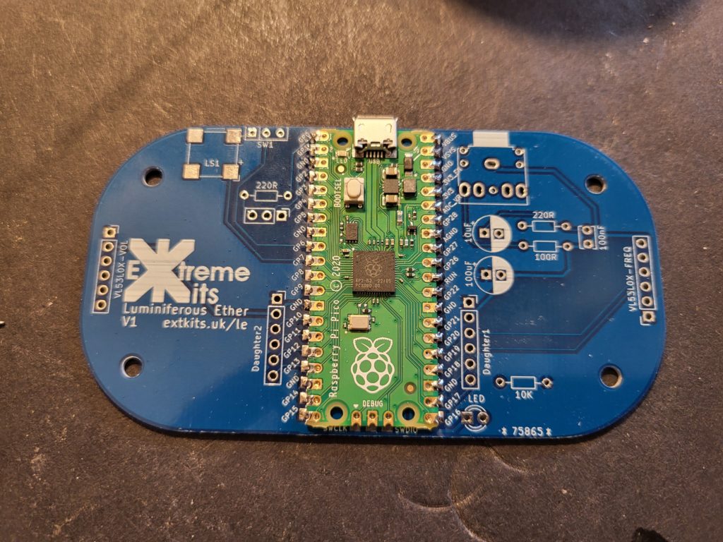
Ensure the PI Pico is central to the pads and carefully solder one of the corner pads.
Check the alignment again and if you are happy, solder the diagonally opposite pad.
If you are happy that all of the pads are aligned centrally with the PCB, solder on the rest of the PIPICO’s pads to the PCB ensuring there are no shorted pads.
Take the 100R,220R, 10K resistors
100R220R
10K
Push the legs of the resistors through the holes in the PCB and solder flush to the rear.
NOTE: The 220R resistor to the left of the PICO or the 3 way connector near it, is Not required.
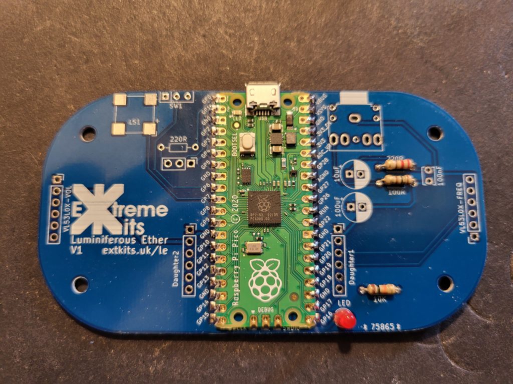
Solder in the Red LED, ensuring that the shorter leg of the LED goes to the square pad on the PCB.
On PCB 1A, there is an additional pair of 4k7 ohm (Yellow,Purple,Red) resistors above the 10K
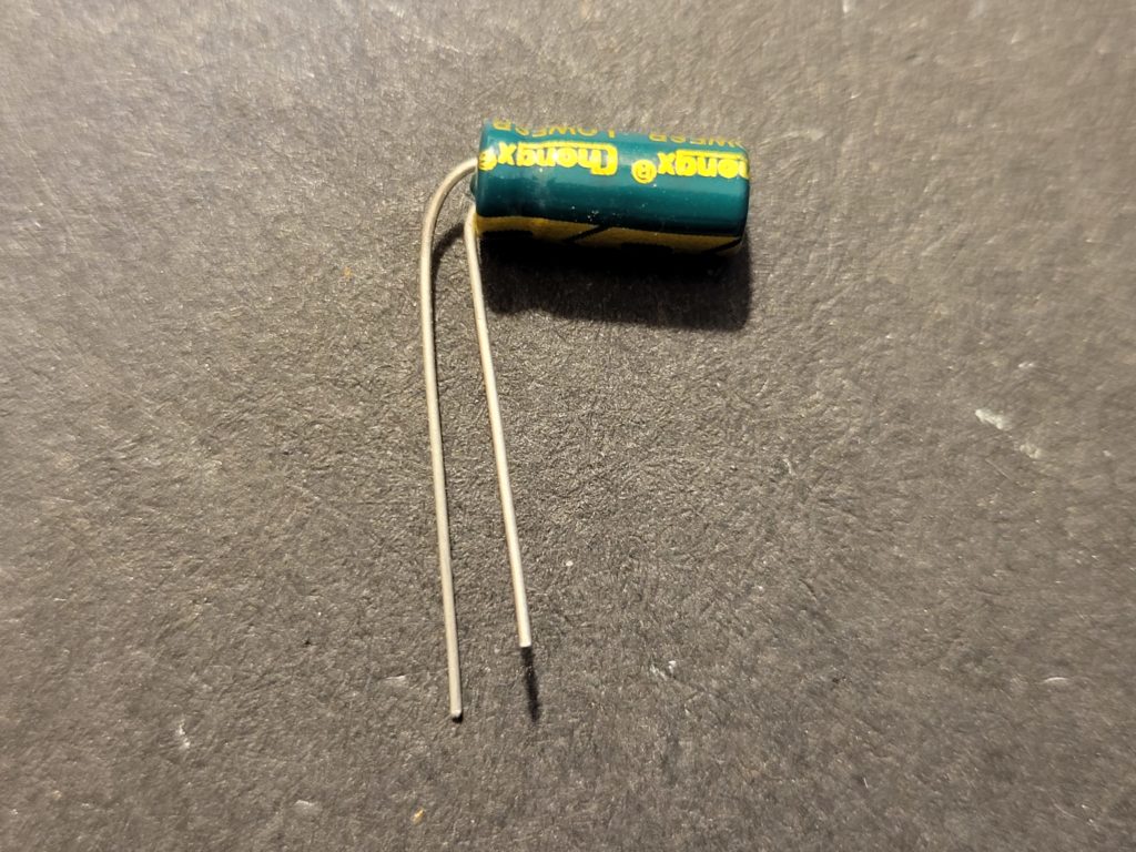
Take the 100uF capacitor and bend the -ve leg at 90 degrees hard to the case. The Positive leg needs to be bent over so they aren’t touching and ideally 2.5mm apart.
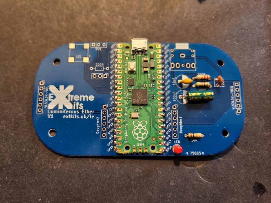
Please the 100uF capacitor horizontally in place as shown.
Solder in the 10uF capacitor, you may need to bend the one of the legs to fit. Although the PCB suggests this capacitor is polarised it does not matter which way around this capacitor is placed.
On PCB 1A, The ident has been changed to a square to match the actual component in the kit.
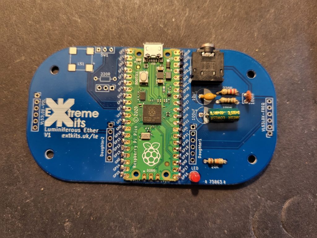
Take the 3.5mm jack socket and solder into place. and the 100nF capacitor as shown.
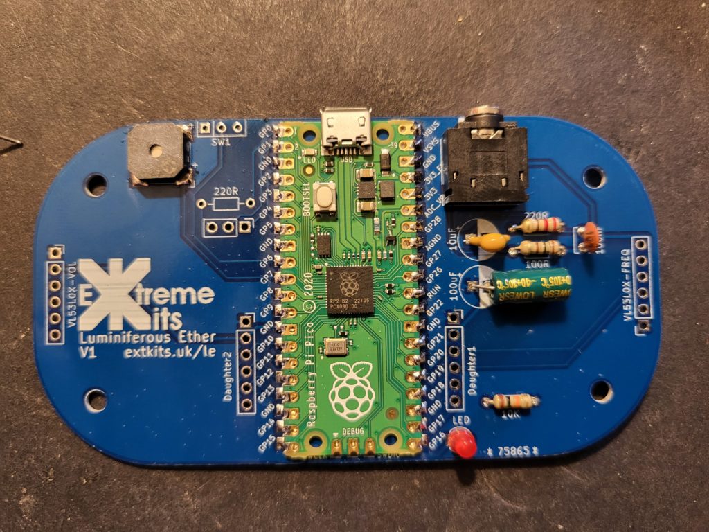
Orientate the sounder and align the + on the case to the + ident on the PCB
Solder each of the 4 pads to the PCB
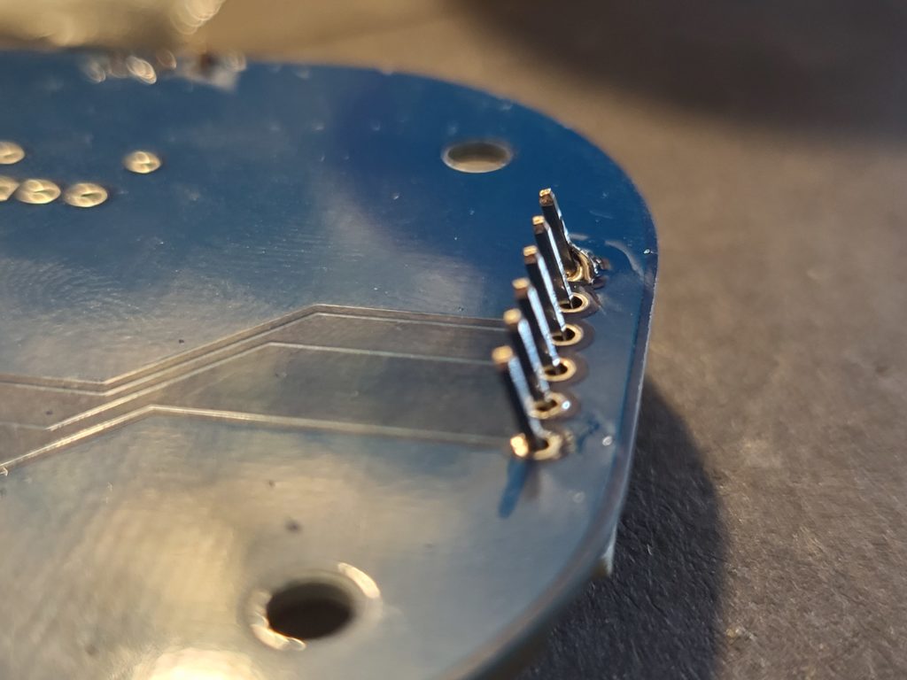
Take one of the 6 x 2.54mm header strips and solder into the PCB at as sharp an angle as the holes in the PCB will allow so the top of the header leans away from the PI PICO on the top of the PCB, Solder in place.
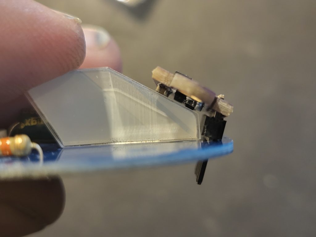
Take one of the two TOF sensors and solder to the top of the header above, again angle the sensor as far as possible away from the PICO
The Sensor should now sit at an angle, you can check this against the guide piece of acrylic in your kit as shown. Be careful not to stress PCB on the TOF sensor.
Repeat the same process with the other sensor.
Solder the switch into place as as shown.
ON PCB 1A, the switch position has changed and is soldered onto the reverse side of the PCB.
At this point put the theremin on to a non conductive surface and power it up from a micro USB.
With the switch (as above) towards the speaker, putting your hands 50mm away from both sensors, you should get some tones from the speaker.
If not check your soldering for missed joints and solder bridges.
If all is OK continue with building the display daughter board below.
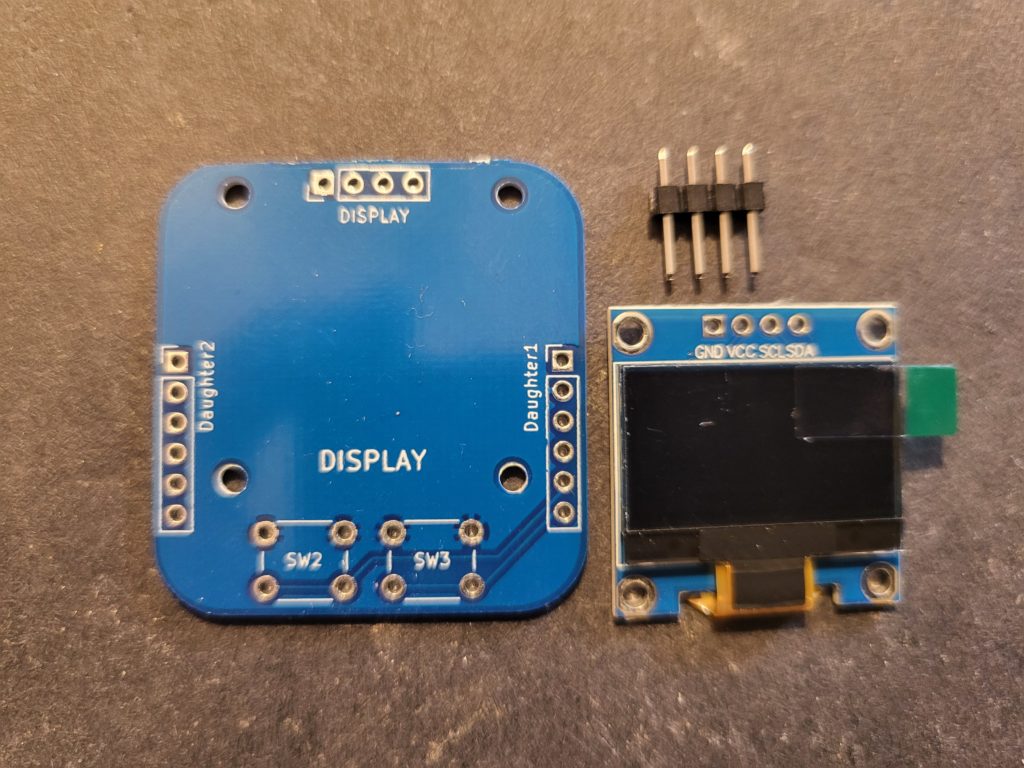
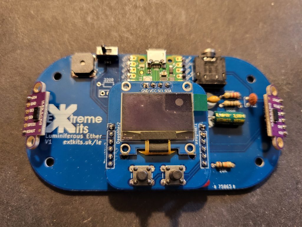
Take the display PCB 4 x 2.54mm header and the display.
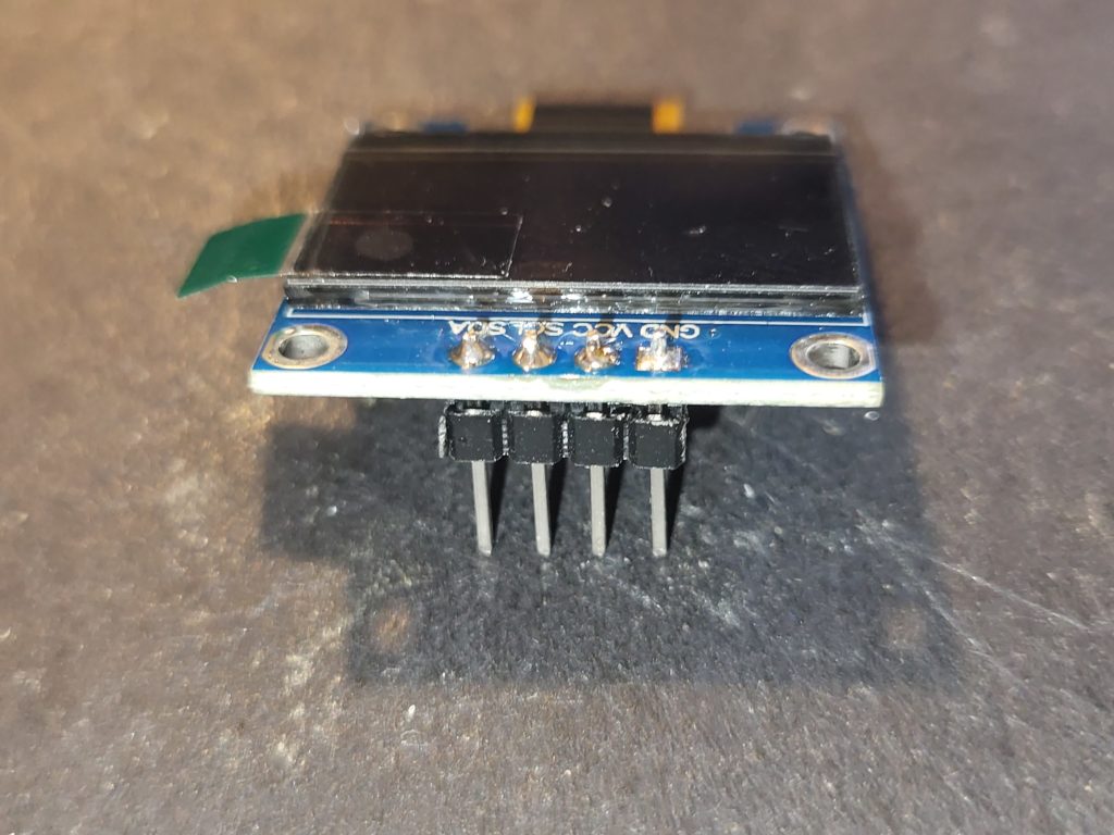
Solder the display to the short end of the 4 way sensor. If possible leave a gap between the PCB and the plastic spacer on the header.
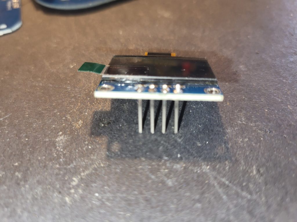
Carefully remove the plastic spacer, leaving the 4 soldered pins.
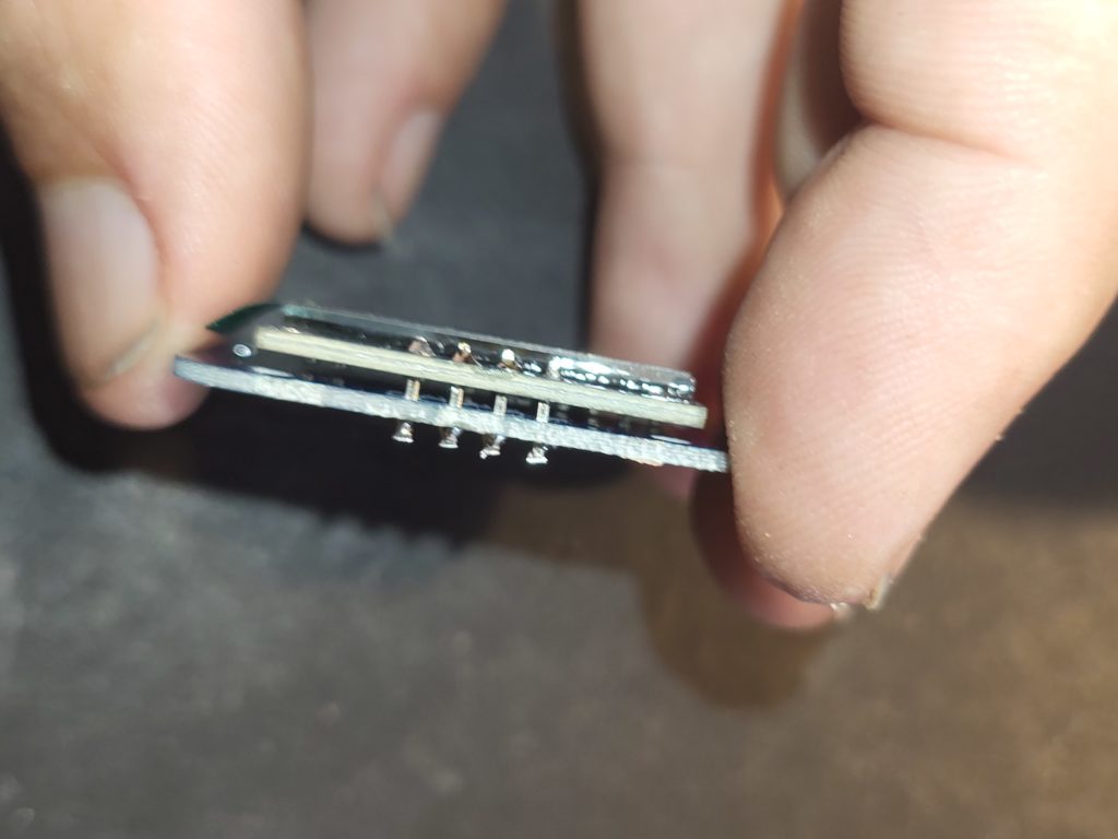
With the display PCB, ensure the word display is on top, solder the display into the display PCB.
So the display is flat and square to the PCB.
Cut off the remainder of the header pins from the underside of the PCB
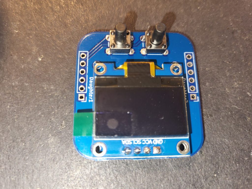
Solder in the two push buttons into the display PCB
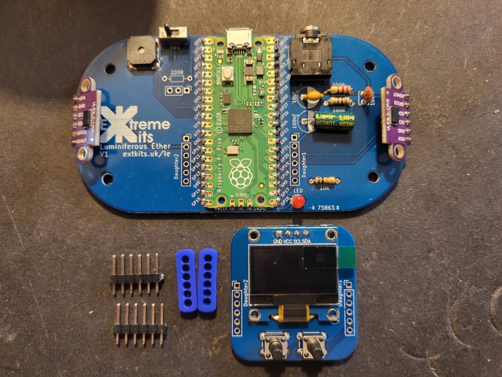
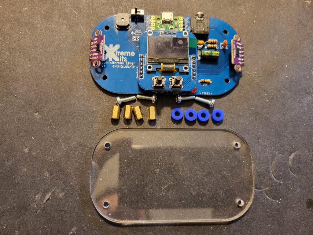
Take the remaining 6×2.54mm headers,a pair of acrylic spacers and the display PCB
Solder in the 6×2.54mm headers with the long ends down through the acrylic spacer as shown.
Then solder the display PCB onto the headers as shown.
At this point you can test your Theremin, just ensure that you have nothing conductive under the PCB and power it up from a micro USB
If all is ok, continue,
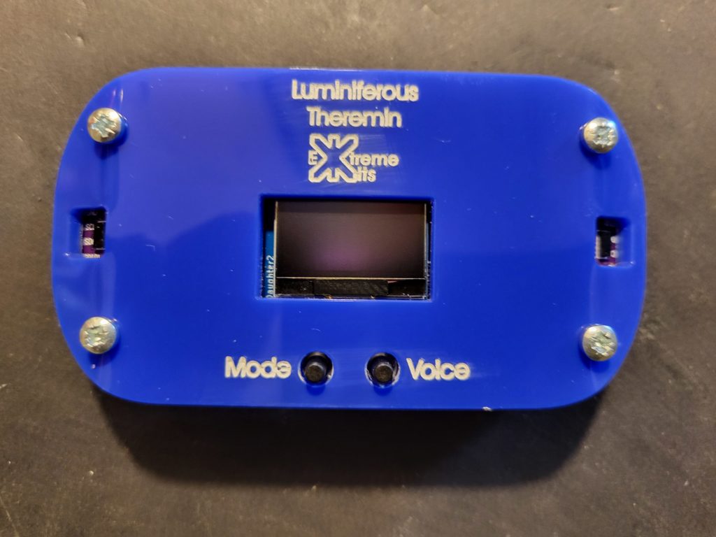
If you are happy that it all works, you can assemble the case.
Take 4 m3x10mm screws, 4 acrylic washers, 4 m3x8mm standoffs and the acrylic base.
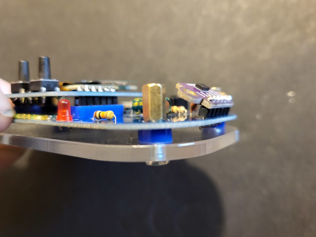
Push the screws through the base, an acrylic spacer and the PCB, secure with an m3 standoff.
Repeat this for all four corners.
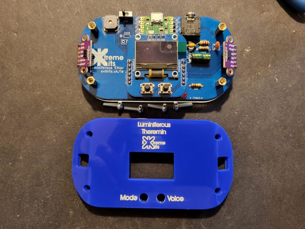
With the 4 remaining m3x10mm screws attach the case lid to the 4 x standoffs.
Don’t tighten too tight as you may damage the display of the TOF sensors.
To finish your Theremin, stick the four silicone rubber feet to the base of the theremin.
PCB 1A only …..
Extra bonus and undocumented component 🙂
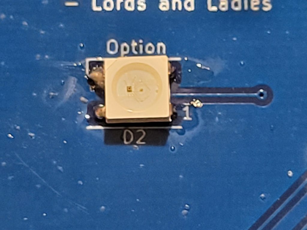
There is a Neopixel supplied with the kit. It is a little difficult to solder in and your kit will work fine without it.
To solder in this LED, with a small soldering iron tip, first apply some solder to one of the PCB pads. Offer up the LED with the cutout corner to the top right (NOT near pin 1) as the picture shown.
Carefully apply your iron to the tinned pad until the Neopixel sits flush with the PCB and aligns with the other pads.
Carefully apply solder to the other PCB pads so the solder flows under the LED and makes a good joint.