

Take the PCB and ensure it is clean and undamaged.
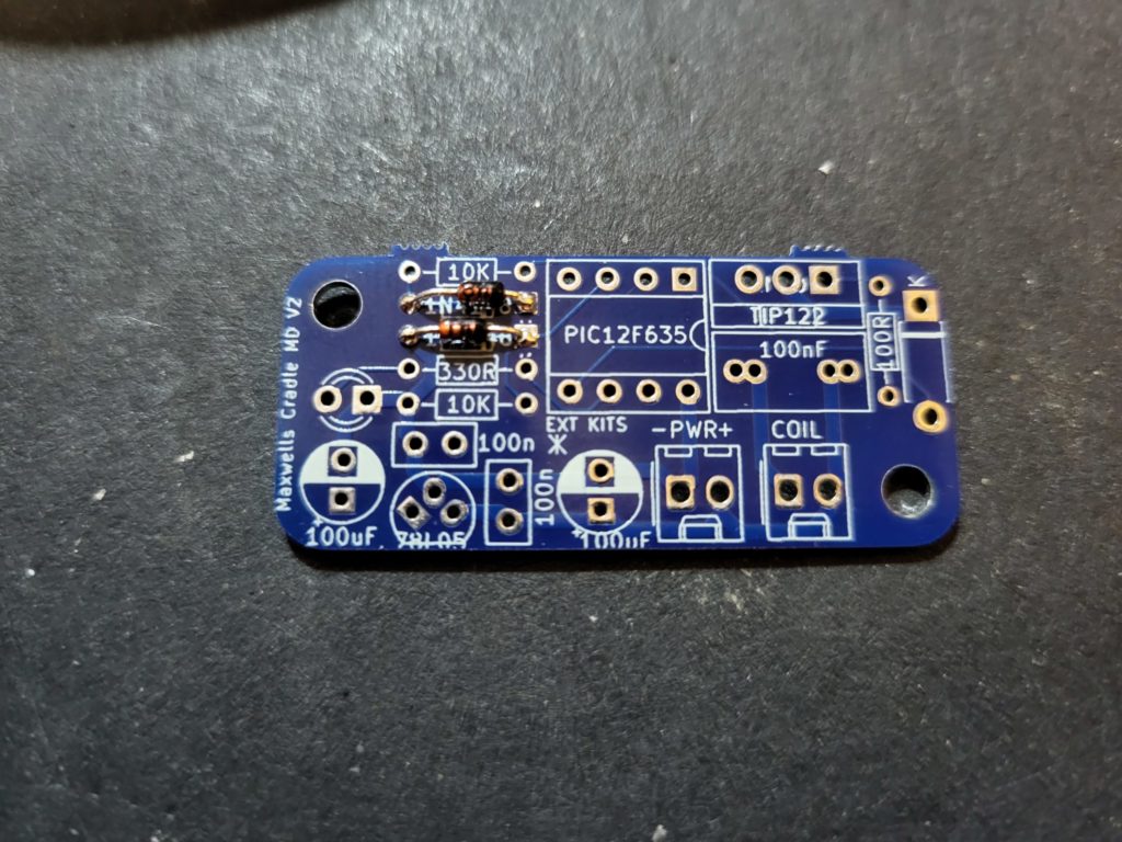
insert the two 1N4148
diodes ensuring that the black line designating the cathode matches to the PCB ident and solder in place.
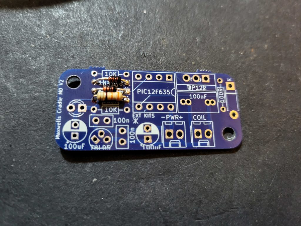
Add in the
330Rresistor and solder in place.

Add in the two
10Kresistors and solder in place.
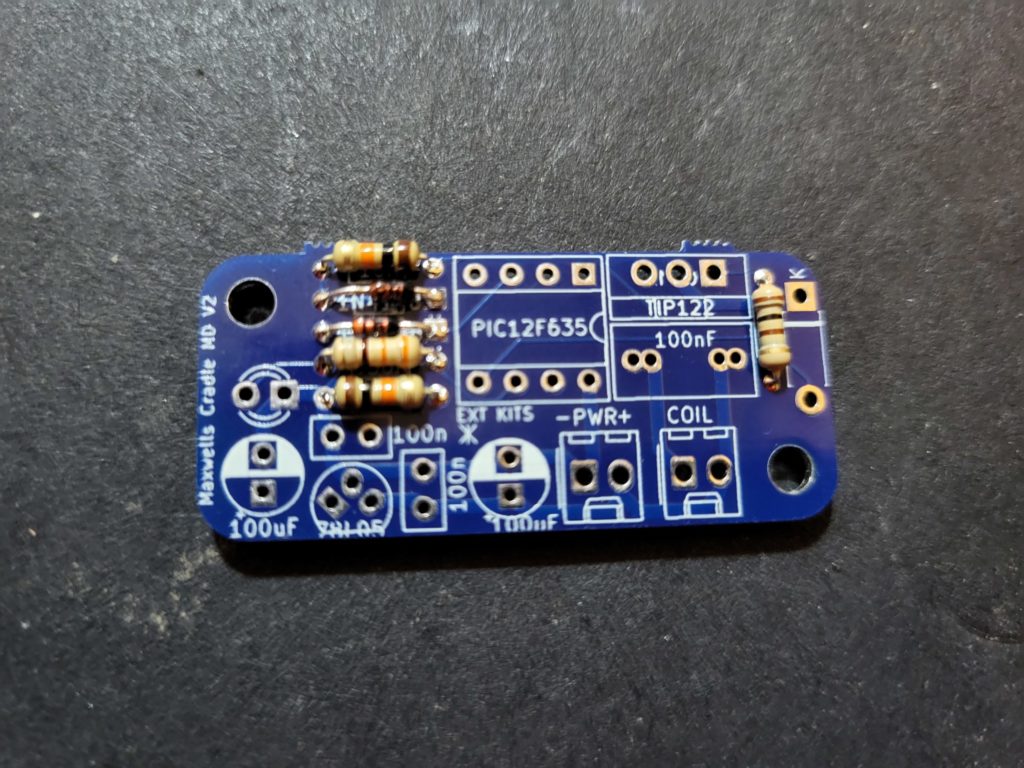
Add in the
100Rresistor and solder in place.

Add in the 1N4007
diode, ensuring the white band matches the white band on the PCB and solder in place.
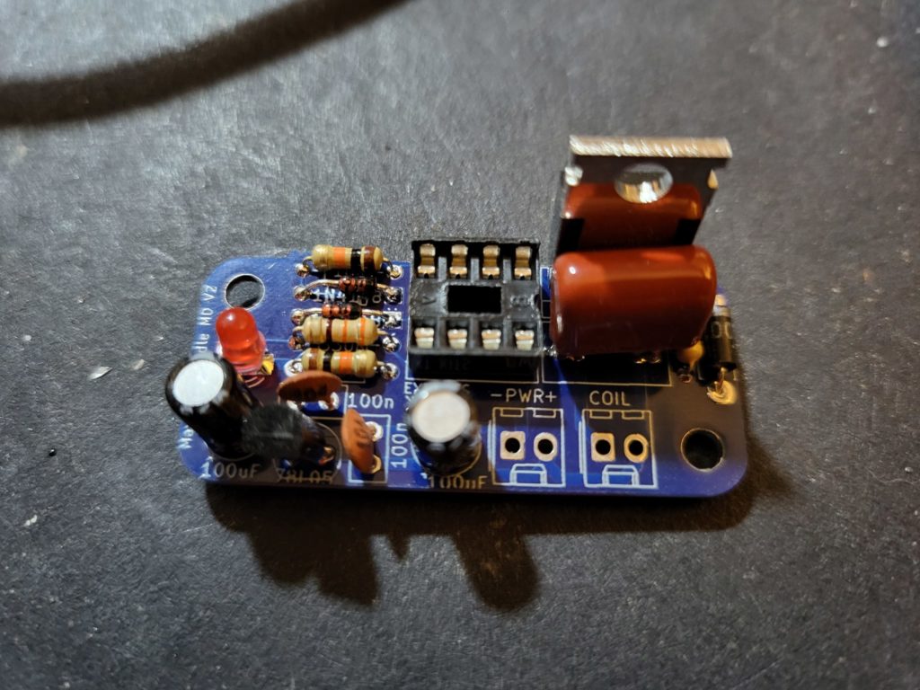
Take the 8pin DIP socket ensuring that the semi-circular cut out at one end, matches the PCB ident.
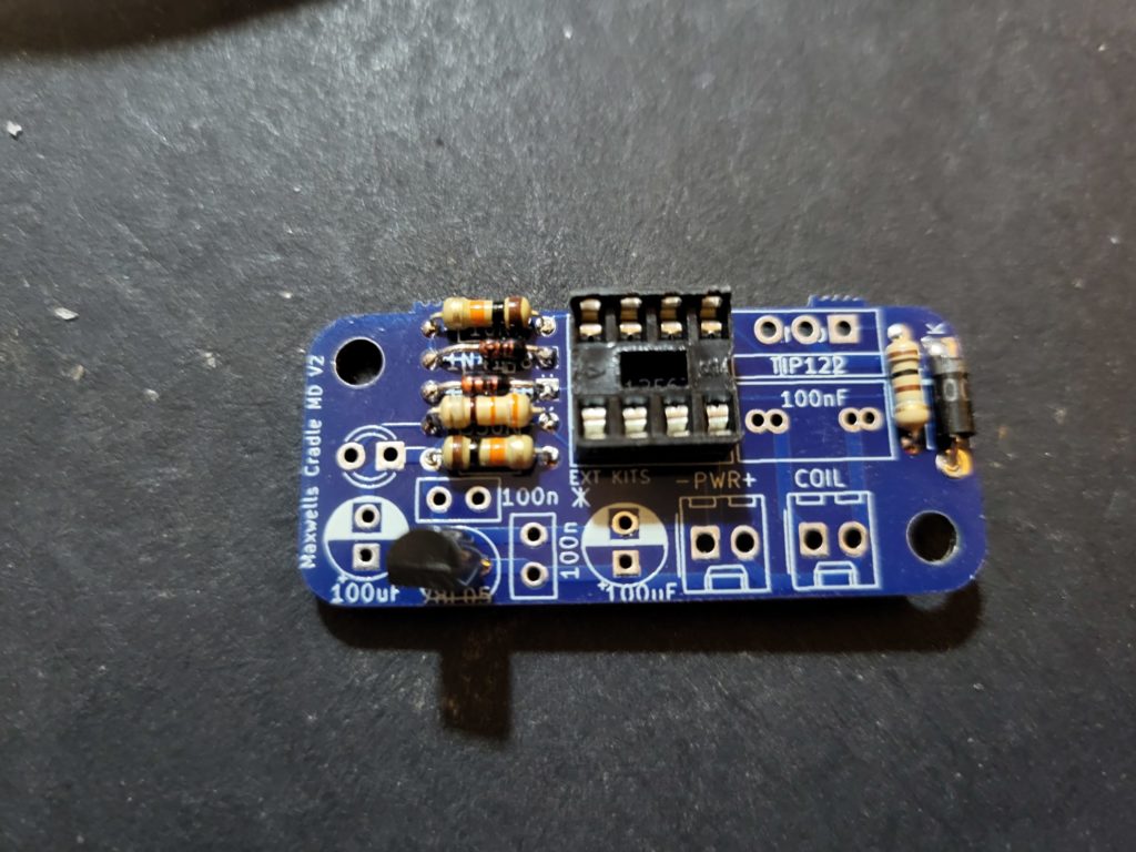
Solder in the 74l05 regulator, ensuring the D shape of the plastic package matches the D shape on the PCB ident.

Add in the two 100nF capacitors and solder in place.
Solder in the TP122 Transistor with the metal tab towards the centre of the PCB.
Add in the LED ensuring that the short leg (cathode) is connected to the square pad on the PCB
Insert and solder in the two 100uF capacitors, ensuring the white stripe is lined up with the white filled semi-circle on the PCB.
And the large red 100nf capacitor.

Solder in the power connector, ensuring the tab is nearest the edge of the PCB.

Taking the Coil, trim the leads to 50mm, and taking a sharp knife or stanley blade scrape off the enamel insulation for 5-10mm. and tin the ends with your soldering iron.
Note: The enamel will be removed by heat, but getting the wire hot enough to do this is easier, if you remove some of the enamel.

Solder in the coil to the PCB as shown the polarity is not important.