
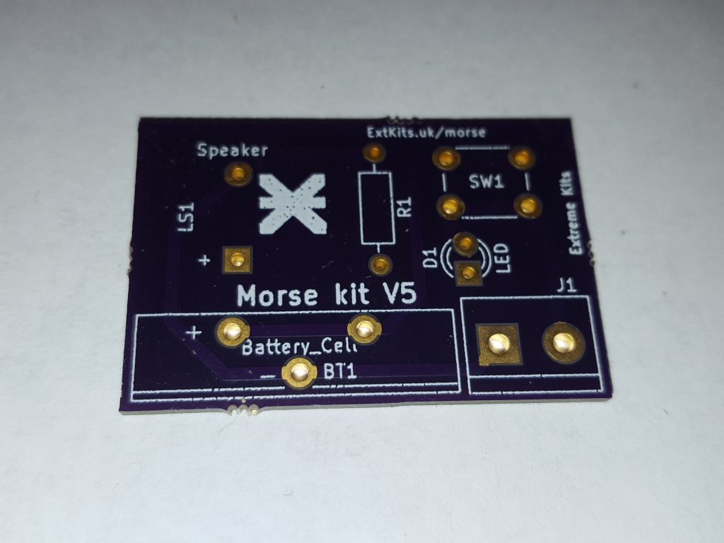
The empty Morse test PCB (printed circuit board) component side up (This is the side you put the components on to).
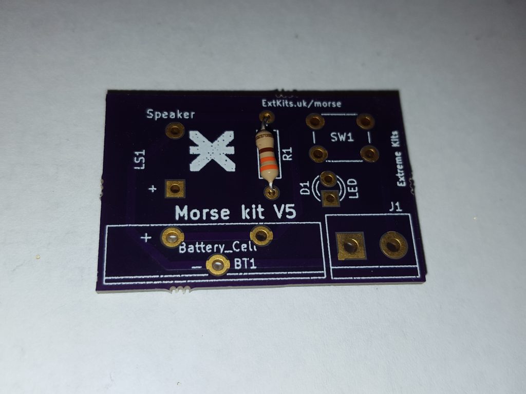
First find the
330Rpush the leads through the two holes on next to R1 on the PCB
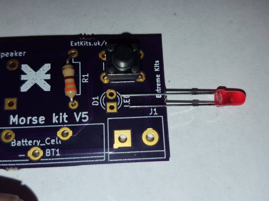
Fit the LED next, be careful to get it the right way around, The short leg needs to go into the hole with the square solder pad. Solder these components ensuring that you haven’t bridged the connections. and cut off the leads just after the solder joint.
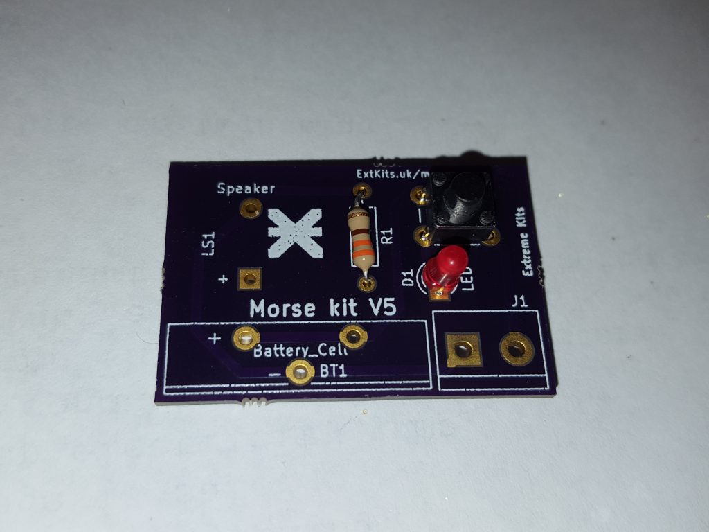
Add the Push button into the four holes to the right hand side of the PCB

Insert the sounder, note the plus symbol on the sticker this indicates the positive(+) lead. This lead needs to go towards the hole on the PCB with the + near it. Solder the leads behind, and again cut off the leads flush to the solder joint.
Check that the speaker is the correct way around.

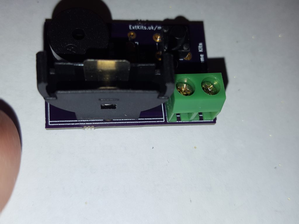
Solder in the Two pin terminal block
Push in the battery holder, All three legs must go completely through the board so the bottom of the holder is flat to the PCB. Solder it in place

On the Underside of the PCB, make sure all legs have solder on them, that there are no long leads left and there is no solder blobs connecting any two pins. (especially check the led connections as these are the two closest together.)
Offer up the battery to the battery holder, ensuring you have matched the + on the battery with the + on the holder.When you are are you have it the right way around, push it fully into the holder.
Note: Putting the battery in the wrong way around, or if the sounder is in the board the wrong way around may damage the sounder.