
Please be aware : The aim of a Nano probe is to give you an idea what a signal is doing on a pin, it is not a precision instrument. All readings will be approximate.
Power Supply
The Nano probe will work from either 3v3 or 5V. It will auto detect the power supply used on power up. The initial splash screen will display the detected voltage. There is a reverse polarity protection diode, but this will short out the power. Put this another way, be careful to always connect the supply the right way around. The Nano Probe takes around 10mA
Any supply from 3V to 5V will work, but the voltage readings will be inaccurate.
Using supplies over 5V will damage your Nano probe.
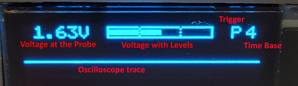
Time Base
The Time base can be set with the top button, from 0-9, timings below are approximate and cover an entire sweep of the display.
0 – 200mS
1 – 100mS
2 – 45mS
3 – 28mS
4 – 18mS
5 – 9mS
6 – 4.5mS
7 – 2.7 mS
8 – 1.8 mS
9 – 0.9 mS
Logic Levels
By default the Nano probe shows a voltage level of half the power supply. This is what you will read when the probe isn’t connected.
The logic levels are shown by the red and green LEDs and follow where possible the common voltage levels for low (green) and high (red)
5V Supply
– any signal below 0.8v will be low (green)
– any signal above 2.5v* will be high (red)
*this is raised slightly from the more correct 2.4V, so the no connection level doesn’t show as a logic high.
3V3 Supply
– any signal below 30% of VCC will be low (green)
– any signal above 70% of VCC will be high (red)
The voltage display indicates these levels with dotted lines.
Trigger
The bottom button selects the triggering scheme
C – Free running constant
P – Triggered by a +ve logic level
N – Triggered by a -ve logic level
S – Triggered by a small absolute change
T – Triggered by a large absolute change
Holding the trigger button will turn off triggering, until it is pressed again.