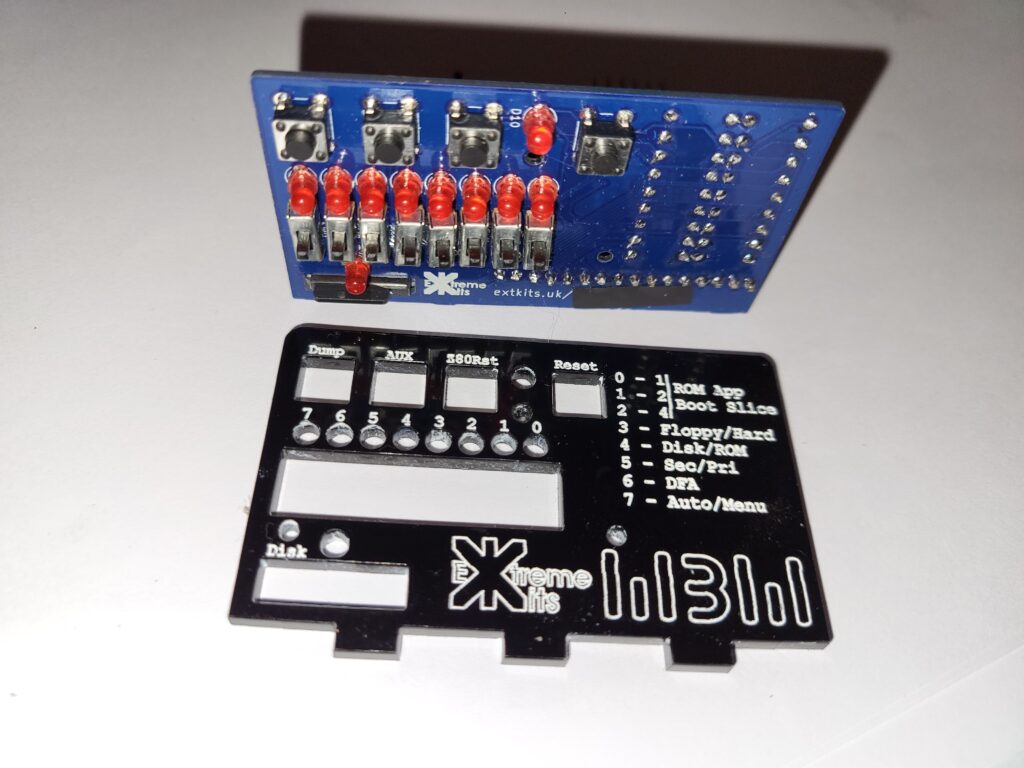
Take the completed PCB and the front panel.

Push the switches and LED’s carefully through the hole sin the front panel and make sure its flat to the PCB.
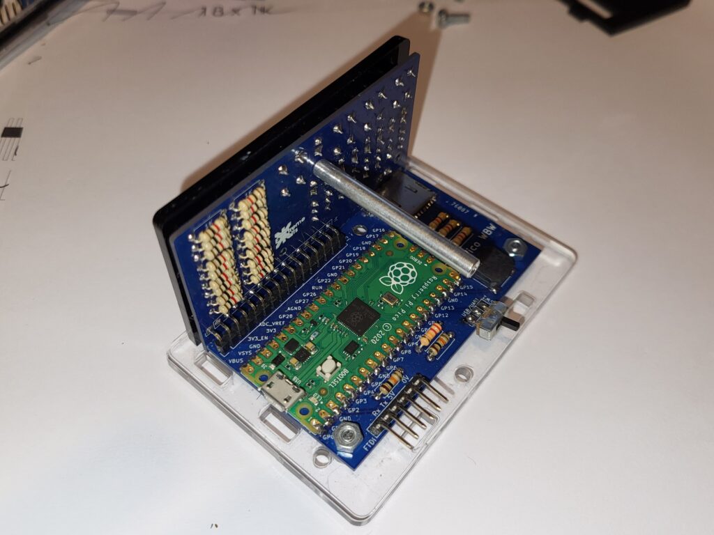
Push the front panel tabs into the slots in the base.

Secure the rear of the PCB with the 2x 3mm acrylic spacers and 2 x 10mm M3 bolts and M3 nuts.
Leave these loose for now, to allow fitting of the case.

With 1x m2 10mm bolt pushed in from the front panel through the PCB, screw in the 40mm m2 spacer.

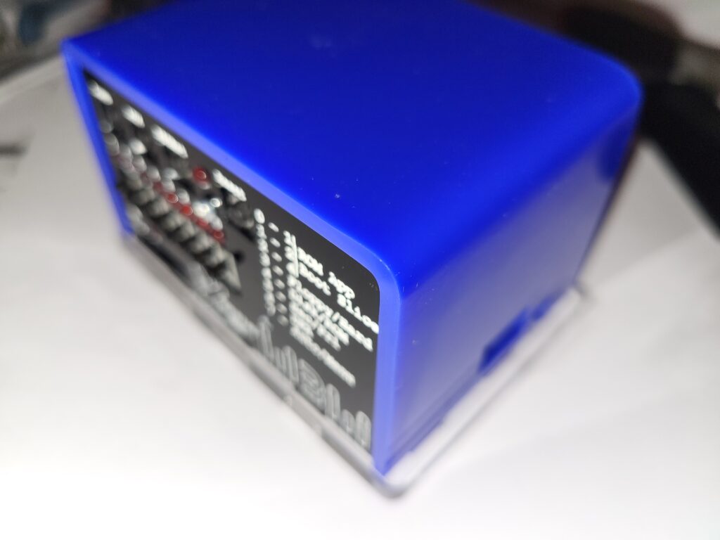
Place the blue acrylic case top and push the tabs into the base.

Secure the case lid with 2 x 10mm m3 bolts and 2 x m3 nuts.
Tighten up the PCB screws/nuts that you left loose.

place the back panel, and secure with an m2 x 10mm bolt into the 10mm standoff.
Apply the adhesive feet to the bottom of the case.
