
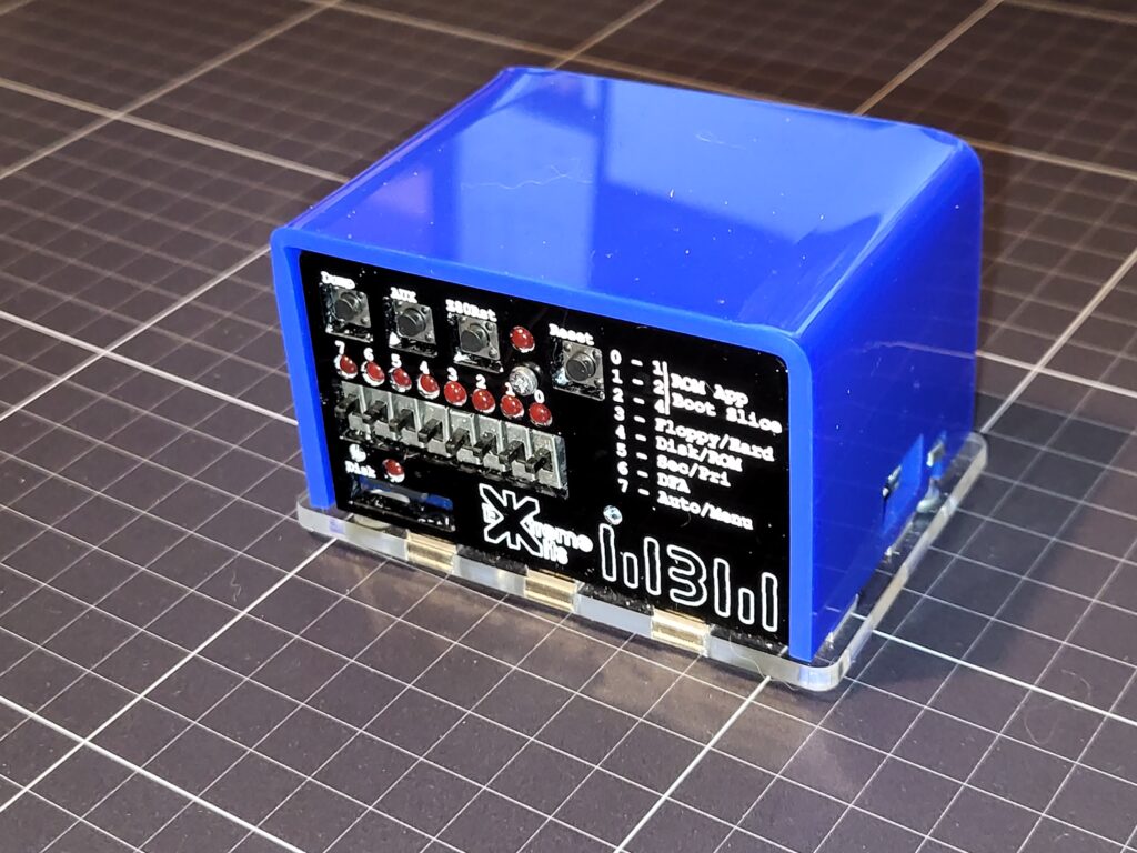
The Pico RomWBW kit.
Pi Pico2 Z80 emulation running RomWBW. SD card for ROM and Disk Images. Speech Synthesis. Front panel LEDS and switches. 2x switchable Serial ports FDTI and USB.
Acrylic or Wooden Case
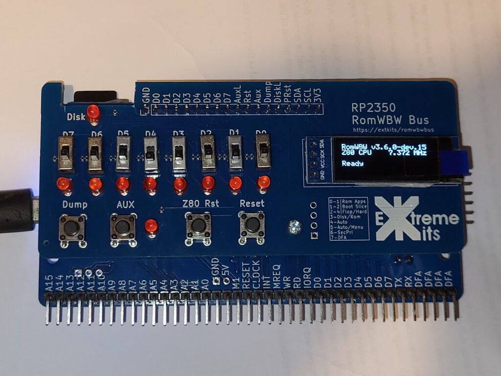
The RP2350 RomWBW Bus kit
Everything from the PicoRomWBW kit plus:-
RC2014 compatible Bus
LCD display (emulation)
Onboard RP2350B (preprogrammed)
No Surface mount soldering. (not even the SD card holder)
PCB only currently – Cases coming soon
Connecting
Connecting by USB or FTDI
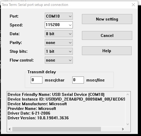
Connecting to the RomWBW bus is as easy as plugging in a micro USB cable, and setting your computers terminal software to 115200, 8 bits, 1 stop bit, no parity to the CDC/pico serial port this is automatically detected.
Windows
On Windows Id recommend Terra Term https://tera-term.en.softonic.com/download
Click on setup -> Serial port to configure your USB connection.
Linux
For Linux Minicom a command line serial emulator , which is likely already installed.
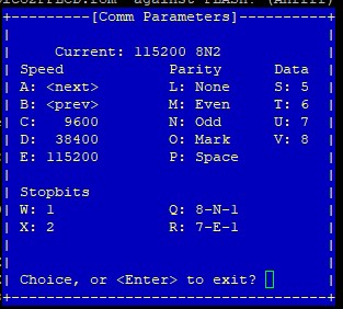
Start minicom with the command minicom -D /dev/ttyXXXX where XXXX is the detected serial port.
then CTRL-A P to setup the serial parameters.
On Board Peripherals
Front Panel
Front panel Switches / LED / LCD Display emulation
Front panel Switches / LED
Writing to Port Zero sets the bits / leds on the front-panel.
Reading from port Zero gives the position of the switches.
Please note that as the 8 lines are shared between the LEDs and switches reading the port will briefly disconnect the drive to the Led’s
5 REM Front Panel LEDs to do CYLON chase
10 FOR F=0 TO 7
20 OUT 0,2^F
30 GOSUB 100
40 NEXT F
50 FOR F=7 TO 0 STEP -1
60 OUT 0,2^F
70 GOSUB 100
80 NEXT F
90 GOTO 10
100 FOR X = 1 TO 50 : NEXT X : RETURN
For more details on how RomWBW uses the front panel, look into the RomWBW manual.
LCD Emulation
The OLED display on a RomWBW Bus system emulates a 16 character x 4 line LCD display. By Default it is set to port 0xDA / 0xDB and emulates the basic functionality of the LCD driver chip (hd44780).
10 R=218    : REM 0xDA - Register
20 D=219    : REM 0xDB - Data
30 OUT R,56 : REM 0011 1000 - Function 8 bit, 2 lines, 5x8 dot font
40 OUT R,14 : REM 0000 1110 - Display on, cursor on, no blink
50 OUT R,1  : REM 0000 0001 - Clear display
60 INPUT "Text to display";T$
70 FOR A=1 TO LEN(T$)
80 PRINT MID$(T$,A,1);
90 OUT D,ASC (MID$(T$,A,1))
100 NEXT A
Sound
Sound, beep, SP0256AL2
SPO256-al2 Speech
Writing bytes from 0-64 to port 0x28 will trigger the appropriate phonym to be played, reading port 0x28 will give a non zero output whilst a phonym is being played.
A tool to compute the phonyms for text speech is here https://extkits.co.uk/sp0256-al2/
5 REM Speak 'RC2040' using allophone data beep port 40 (0x28)
10 FOR A=1 TO 22
20 READ X
30 OUT 40,X
40 WHILE(INP(40)>0)
50 WEND
60 NEXT A
100 DATA 59,2,55,55,19,2,13,48,7,7,11,1,2,13,19,4,40,58,2,13,19,4
Sending a value from 0-127 will change the frequency of the speech roughly clocking the speech from the midi note value frequency .
Beep
Sending a value of 1-127 to 0x29 will send a tone to the speaker, roughly the same frequency as the note values in the midi specification.
10 REM output middle C (256 Hz) Base Port 41 (0x29)
20 REM and turn off afterwards
30 OUT 41,60
40 FOR B=1 TO 200
50 NEXT B
60 OUT 41,0
Neo Pixels
Neo Pixel Driver
NeoPixel Port
But you could connect a string of neo-pixels WS2812 to GPIO 28 on the Pico. and take a look here.
The neopixel data out pin is on GPIO 28. or on the lablled port on RomWBW Bus. This is currently set to support WS2812 / WS2811 LEDS which use 24bits(RGB)
If you wish to use the 32bit LEDS you will need to recompile with WRGB set to true.
The NeoPixel ports are 64-71
| Port | Usage |
|---|---|
| 64 | Data |
| 65 | Cmd |
| 66 | Spare(currently) |
| 67 | Led Address |
| 68 | Pallette Address |
| 69 | Red |
| 70 | Green |
| 71 | Blue |
Commands
| Command | Usage |
|---|---|
| 1 | Set NormalMode |
| 2 | Set Pallette Mode |
| 3 | set repeat |
| 4 | set brightness |
| 5 | Set Number of pixels (Max and default 128) |
| 6 | Spare |
| 7 | Spare |
| 8 | Spare |
| 9 | Spare |
| 10 | info (debug) |
| 11 | Spare |
| 12 | Spare |
| 13 | Spare |
| 14 | Set all from RGB values |
| 15 | All Off (RGB=0) |
Simple usage
Set the number of pixels to X by writing X to Data (port 64) then sending 5 to Cmd (port 65) to a Max of 128
Set Normal mode by writing 1 to port 1 (default)
Set the R, G and B values by writing to ports 69,70 and 71
Write the LED address to diaplay this colour into port 67
Palette Operation.
Set palette mode by writing 2 to port 1
Set Palette entries
Setup the palette by writing to an RGB value to ports 69,70 and 71
Write the Palette address to save this colour into port 68
Using the Pallette
set the pallette address by writing to data (port 64) and write the led address into port 67
Repeat
Repeat automatically copies the first N values (the repeat value) every n leds for the rest of the string.
Send the repeat value to data (port 64)
Send 3 to the Cmd port (65)
Write the LED values or pallette values to the first n LED’s of the string. These will be copied to the end of the string.
all on
Set the R, G and B values by writing to ports 69,70 and 71
Send 14 to the Cmd port (65)
all off
Send 15 to the Cmd port (65)
Brightness
To set an overall brightness (default 255 full on)
write the brightness to Data (port 64) and then send 4 to Cmd (port 65)
Speed
Setting the max number of pixels can increase the speed, as can not setting a brightness (brightness 255)
This can be set either in RGB values, or via the palette.
If you are writing too fast to the driver it will just ignore commands.
Sample Code
100 rem neopixel repeat test
110 OUT 64,3
120 OUT 65,3
130 c=c+1
140 for p=0 to 2
150 c=c+1
160 gosub 2000
170 next p
180 goto 130
200 end


2000 if c=1 then goto 2100
2010 if c=2 then goto 2200
2030 if c=3 then goto 2300
2040 c=c-3
2050 goto 2000

2100 r=32:g=0:b=0
2110 goto 3000

2200 r=0:g=32:b=0
2210 goto 3000

2300 r=0:g=0:b=32
2310 goto 3000

3000 out 69,r
3010 out 70,g
3020 out 71,b
3030 out 67,p
3040 return
Serial ports
USB and FTDI serial ports
The RomWBW emulation has two serial ports USB and FDTI
The USB port connects at 115200, 8 bits, 1 stop bit
The FTDI port also defaults to 115200, 8 bits, 1 stop bit, but can be changed with the INI file on the SD card.
The primary port is USB, this can be changed to FTDI in the INI file.
This can also be changed in the Pico RomWBW by the switch at the back of the unit.
The front panel can also be used to change the port from Primary / Secondary. For more details look at the RomWBW front panel switches. and the RomWBW monitor I command.
RC2014 bus (RP2350 RomWBW bus only)
Connecting and using Rc2014 I/O peripherals
The RomWBW Bus will connect to RC2014 I/O peripherals. It will not work with peripherals that use memory, other processors. There also may be issues with the timing of real time signals.
The RomWBW Bus uses logic levels of 3V3 this will be fine for most RC2014 modules, but some versions of TTL chips may have a problem with this. The lower 8 bit address lines are buffered to 5V as many modules use diode address decode logic.
The RomWBW Bus will first address any i/o port that it is emulating (if its enabled) It will then try to address any module on the RC2014 bus.
Reset
The Reset line is extended from the Pico/RP2350 Z80 line to allow external peripherals to reset the emulation. This is separate from the Pico Run line (which resets the pico)
Halt
Not yet implemented
Interrupts
Not Yet implemented
Wait
The Wait line is not enabled by default, to use it it does need to be enabled (see rc2040.ini) and it needs to be externally pulled high to allow the emulation to run.
Clock
Non synchronised clock runs by default at 7.327 Mhz. See rc2040.ini file settings for more detail.
RC2014 bus card compatibility
The RC2014 ecosystem is huge and not everything works together.
The RomWBW Bus tries to be compatible with as many of the IO cards as possible but there are known issues with some. Memory, processor and clock cards are not supported.
Generally any TTL compatible IO only card will work. Avoid cards with an ATMega processor as their logic levels are not 3v3 compatible.
The RC2014 I/O bus Interface (RomWBW Bus version only)
Power, to/from the Pico RomWBW and RomWBW Bus
Power
The PicoRomWbw and RomWBW Bus can be powered in a number of ways.
Via USB is the easiest way, just plug in a Micro USBcable.
Via FTDI if the link “FTDI power” is shorted, then the device can be powered from an FTDI or compatible cable.
The RomWBW can also be powered from the RC2014 bus. Please be careful as this can also back feed power via the USB connector. This can be isolated by cutting JP1.
RomWBW Bus
It is also possible to run the RC2014 bus from 3v3 by shorting the other link of JP1, but not only do the RC2014 peripherals need to run with 3V3, but you must be extremely carefull not to connect 5V to the RC2014 bus as this will damage the Controller.
Signals to the RC2014 Bus (RomWBW Bus only)
CLK
A 7.32Mhz (approx) signal. Not synchronous withe the bus activity
D0-D7
Data bus, bi-directional 8 bit data bus. Works at 3V3 levels. 5V tolerant.
A0-A7
Address lines used for IO address decoding only. 5V out.
A8-A15
Address lines, not needed for I/O operations, therefore tiled to 0v Via 10K resistors.
MREQ
MREQ line is held high during IO operation,tied to 5V via 10K resistor.
IORQ
IORQ line is brought low when data is read or when data is required from the I/O operation,3v3 signal output.
RD
Read line is brought low when reading I/O data. 3v3 signal output.
WR
Write lines is brought low when writing to an I/O device,3v3 signal output.
RESET
Tied to the Z80 Reset button, Pulled low to reset, Tied to +5V via 10K resistor. 5V/3v3 line.
M1
M1 is brought high during an IO cycle, otherwise it is low. It is not driven during memory cycles and stays low. 3v3 signal output.
Emulated and external Z80 I/O Ports
Disabling ports, changing emulated port numbers, external ports (bus version only)
The ports that the emulated peripherals respond to each have their own settings in the ini file.
To change an emulated peripheral i/o port location, set the appropriate port.
To disable an emulated i/o port, set the port number greater than 255.
External i/o ports (Bus version only) are contacted when a request is made for an i/o port not configured for any emulated i/o peripherals. The i/o ports for the external devices must be set by address bus decoding on the i/o peripheral card itself.
RP2350 / Pico software
Pico / RP2350 emulation software – Github repository
The code for the Pico/Pico2 and RP2350 emulation is available on github.
PicoRomWBW https://github.com/ExtremeElectronics/RC2040-ROMWBW. (Pico and Pico2)
RomWBWBus https://github.com/ExtremeElectronics/RomWBW-Bus. (On Board RP2350B only)
Pico / Pico 2 (Pico RomWBW only)
Using Pico RomWBW the processor rp2040 or rp2350 must be selected in the CMakeLists.
Also note that you must use the appropriate rom file to match the Pico Board/Processor as the Pico2 (rp2350) has much more memory available.
RomWBW Bus will only work with the RP2350B processor from the RomWBW Bus repository, and requires the Ext Kits PCB
SD CARD Files
diskdefs, CPMIDE.id, img files rom files
CPMIDE.id
This file contains the disk geometry for the SD card file system
Python programs to read and write the id files are here https://github.com/ExtremeElectronics/RC2040-ROMWBW/tree/main/Support%20Programs
diskdefs
The diskdefs file allow the FFS system to read the CPM disks with in the img. They follow the CPM tools diskdef specification and can also be used with CPM tools to read an write to the img files.
img file(s)
.img files are the flat file representation of the disk drives. Each img file can hold a number of disk volumes. Take a look at the RomWBW descriptions for more information. https://github.com/wwarthen/RomWBW/tree/master/Doc – Hard Disk Anatomy
.img files are generally created by the RomWBW system creation workflow and can be loaded into an SD card. See the RomWBW Github for details.
rom file
.rom files are compiled by the RomWBW system creation workflow and contain the executable CPM “BIOS” for the RomWBW system. They are created specifically for the system that uses them and are configured with the peripherals and memory details. See the RomWBW Github for details.
RC2040.ini
The Rc2040.ini file and settings
The ini file is a standard ini file format. It can be either RC2040.ini or RC2014.ini, RC2040 will take preference in the RomWBW systems. Rc2014.ini is accepted for compatibility with the RC2014 SD card interface.
Each section of the ini file is delimitated by a name in square [] brackets. followed by a number of settings each on their own line and ending in a ‘;’
Settings are of the form name = value ;
String values must be enclosed in double inverted comas.
Comments can be added to and line as long as the first character is a ‘#’ the rest of the line will treated as a comment and will be ignored. Blank lines are accepted, and ignored.
All settings have a default value if not referenced in the ini file.
An example of an ini file follows.
#
# RC2040 configuration #
#

[IDE]
#enable IDE
ide = 1 ;
idefilei = "CPMIDE.id";
idefile = "hd1k_combo.img";

#rom file as ROM source
[ROM]
romfile = "RCZ80_std_pico2FPLCD.rom";

#Size of ROM
romsize=0x80000; //512k

[CONSOLE]
#port 0=UART or 1=USB
port = 1;

[EMULATION]
# Serial Type ACIA=0 SIO=1;
serialtype = 1;

inidesc="ROMWBW 1K SIO CPM RP2350 ";

[SPEED]
#Pico overclocking *1000 Mhz
overclock = 250;
IDE settings
[IDE]ide : 0 don’t use IDE interface / 1 use IDE interface
iscf : 0 use separate CPMIDE.id file / 1 use old CF format with id file as the first 1024 bytes
idepathi : name of CPMIDE.id file
idefile : filename of disk image
idefile1 : filename of secondary disk image (optional)
ROM settings
[ROM]
ovjump : on Rc2040 kits allows the ini file to override the PCB jumpers.
romfile : Rom image to load and boot into.
romsize : Size of rom file in hex. e.g 0x1000
jumpto: jump to address on start of emulation in hex e.g 0x0ff0. Usually 0 on z80 systems.
EMULATION settings
[EMULATION]
inidesc : string description describing ini file shown at boot.
serialtype : 0 Emulate ACIA / 1 Emulate SIO
CONSOLE settings
[CONSOLE]
port : 0 default serial port is USB / 1 default serial port is UART (FTDI)
OverClock Pico Setting
[SPEED]
overclock : 0 No over clock / speed in Mhz to overclock processor (use with caution). Usually Ok to 250. Seams to affect SD Card first.
UART Settings
[UART]
BaudRate : 300 to 115200 (defaults to 115200)
DataBits : 7 / 8
StopBits : 1 / 2
Parity : 0 off / 1 on
PORT Settings
Set Z80 port address (0-0xff) in hex. Setting a port greater than 0xFF disables the peripheral.
[PORT]
pioa : address of IO Port for front panel LEDs and switches.
spo256 : address of the SPO256AL2 speech synth emulation
spo256freq : address to set the SPO256AL2 speech synth frequency
beep : address to set the beep port.
Neo : base address of the neo-pixel driver ports.
DisplayReg : address of the LCD emulation Register port
DisplayData : address of the LCD emulation Data Port
InvSwitches : inverts the front panel switches
RC2014 bus settings
[BUS]
IoSleep : delay in uS between control signals and data for the external RC2014 bus.
wait : 0 disable wait line / 1 enable wait line.
ClkFreq : frequency of the Clock line on the bus in Khz, defaults to 7372 (7.372 Mhz)
Debug Settings
[DEBUG]
trace : 0 trace off / 0x000001-0xffffff set various trace bits
TRACE_MEM       0x000001
TRACE_IO        0x000002
TRACE_ROM       0x000004
TRACE_UNK       0x000008
TRACE_CPU       0x000010
TRACE_RTC       0x000040
TRACE_SIO       0x000080
TRACE_CTC       0x000100
TRACE_IRQ       0x000400
TRACE_UART      0x000800
TRACE_IDE       0x002000
TRACE_SD        0x008000
TRACE_PPIDE     0x010000
TRACE_ACIA      0x400000
TRACE_BANK      0x800000
watch : 0 no watch : 0xNNNN set Memory location to watch
Sound Settings
[SOUND]
disksounds : 0 disk sounds off / 1 disk sounds on
RomWBW (CPM “BIOS” software)
RomWBW, getting, compiling, documentation
Compiling RomWBW
To compile a new set of rom and CF images clone the ROMWBW repository from here https://github.com/wwarthen/RomWBW and copy the asm files from https://github.com/ExtremeElectronics/RC2040-ROMWBW/tree/main/Compiling-custom-ROMWBW to the /Source/HBIOS/Config directory. Run the ROMWBW build using the guide in readme in the root of the ROMWBW repository.
After selecting RCZ80 it should give an option to use RCZ80_std_pico or RCZ80_std_picoFP (for front panel support)
Run the rest of the compile and copy the files RCZ80_std_pico.rom and RCZ80_std_pico.rom hd1k_combo.img from the BINARY directory to the RC2040’s SD card
Check the RC2040.ini and ensure the settings point to the new rom and img’s
I haven’t tried the other image options, but I don’t see why they shouldn’t work.
Emulation Software Updating
In general you can update the emulation software by connecting your PicoRomWBW or RomWBWBus to your computer whilst pressing the “boot” button on the processor board.
This will connect a usb external folder that you can drop in a new uf2 file into.
In the root of each github repository there will be a compiled uf2, download and copy this file into your usb folder.
Be careful to download the correct uf2 file
Pico RomWBW either RomWBW2040.uf2 for Pico or RomWBW2350.uf2 for Pico2
RomWBWBus will have a similar uf2 file in its root.
USING CPM and Common CPM software
CPM, BASIC, FORTH,
BASIC
FORTH
CPM
External Tools
CPM Tools, CPM disk manager
CPM Tools
CPM Disk manager