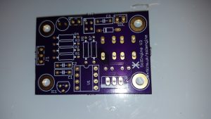
 Bare PCB for the Solenoid engine
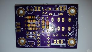 Add in resistors as shown (R5’s value has now changed to 330Ohm (Orange Orange Brown)
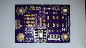 Solder in the IC holder ensuring the divot in the holder points towards the * for pin 1
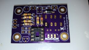 Solder in the Diode, ensuring that it is in the correct way around
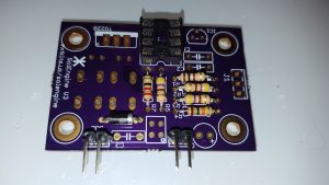 Solder in the two 90 degree edge connectors.
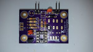 Solder in the three 100n Capacitors and the 5v regulator
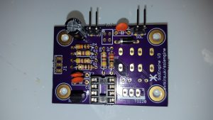 Solder in the electrolytic capacitor
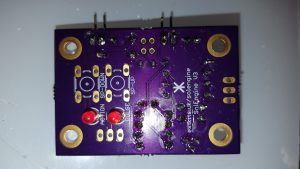 Flip the board over and solder in the two LEDs ensure that the cut out (cathode) points towards the IC holder
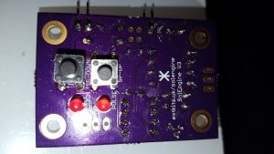 Solder in the two buttons (hopefully better than they are soldered in this photo!)
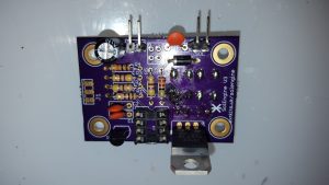 Flip the board back and solder in the transistor ensuring the heat sink is along the edge of the PCB
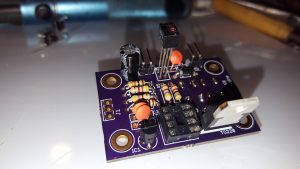 Solder in the optical proximity detector. leaving the base of the detector 15mm away from the board.
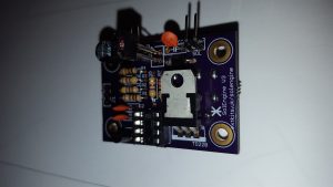 The Completed PCB
Final step, solder your solenoid to the SOL output pins, and a supply to the 6-12v pins, ensuring it is connected the correct way around.
.
.
.
.
.
.
.
.
.
.
.
.
.
.
.
