
These instructions are outdated and incomplete, they are retained for reference only
the up to date instructions are here
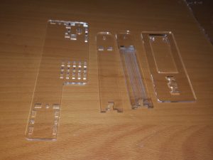 Start with the top base, two pillars and the gallery.
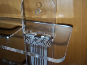 Insert one of the columns through the gallery
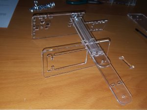 Insert the second column through the gallery
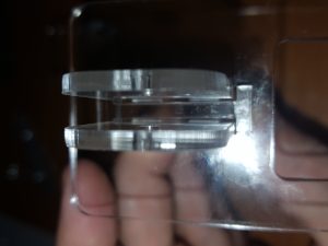 and secure with the I beam. You may want to secure the I beam in place with a small piece of tape whilst building the rest of the kit.
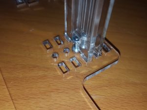 Screw the column bases to the base top with 10mm m3 nuts and bolts as show. Make sure the columns fit into the slots shown.
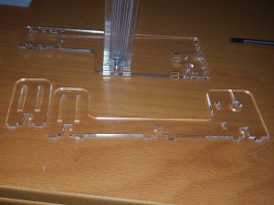 Take the Solenoid Mount plate and upright frame
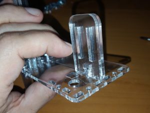 and place them into the slots shown
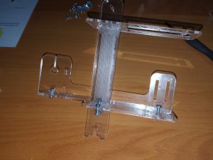 Bolt into place with 2 x 10mm m3 bolts, add the centre plate and bolt into position with a single m3 x 10 mm bolt.
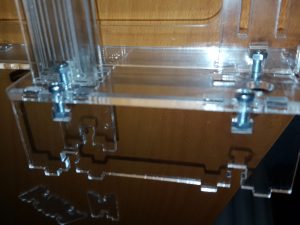 Bolt on the front plate with 2 x 10mm m3 bolts
 bolt on the left end plate 2 x 10mm m3 bolts
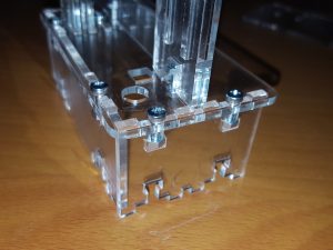 bolt on the right end plate 2 x 10mm m3 bolts
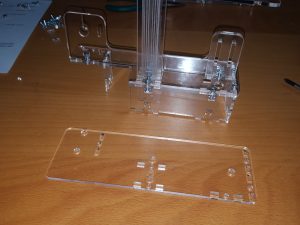 take the bottom plate
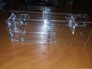 and bolt it onto the left,centre,front and right plates with 6 x 10mm m3 bolts
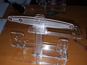 Take the beam and bolt in in the centre
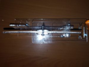 with a single 16mm m3 bolt and a nylock nut. Tighten to allow movement
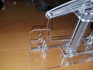 at the flywheel end of the engine attach the 75mm long pull rod to the beam with a single m2 x 10mm and nylock nut
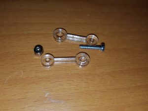 take four 15mm linkages two m2 10mm bolts and two nylock nuts
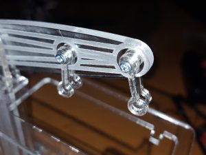 and secure to the beam, tighten to allow movement
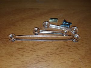 Take the 50mm push rod, and two 25mm linkages, a 6mm m2 threaded standoff and two m2 x 8mm bolts
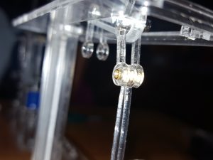 push the standoff through the two linkages on the beam with the push rod in the centre
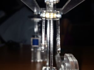 screw in the two 25mm linkages at either end of the standoff using the m2 x 6 mm bolts
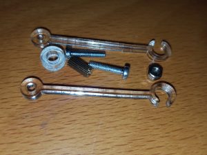 take the two 35mm open ended linkages, a m2 standoff, a 3mm thick spacer and two m2 x 8 mm bolts
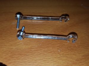 insert the m2 x 8mm bolts through the open ended linkages
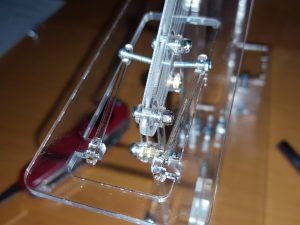 Clip the linkages on to the turrets on the gallery
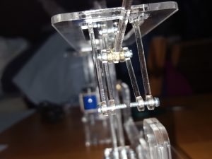 Push the m2 bolts through the hanging 25mm linkages
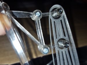 swing the linkages to the m2 stand-off, put the 50mm push rod in the middle (on the stand-off) and screw together
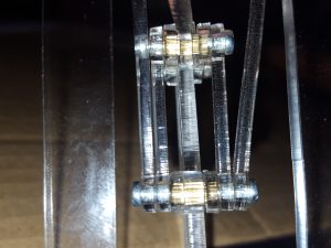 View from underneath of the completed linkage
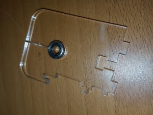 Press one of the bearings into the rear bearing block
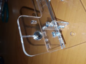 press the other into the upright frame
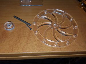 Take the 20mm m2 bolt the flywheel, axel and the hub
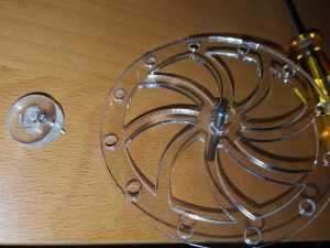 Push the axel through the flywheel and put the m2 bolt through the hub
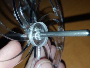 Push the hub on to the axel and through the flywheel, secure tightly with an m2 nut.
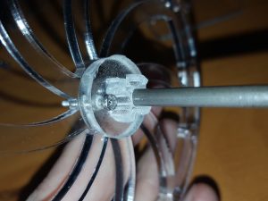 place a star spacer on the head side of the hub
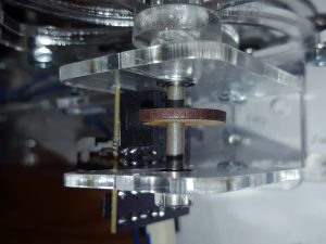 Slide the axel through the upright frame and slide the cam to the middle of the axel.
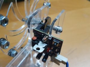 Fit the PCB into place using the registration holes/tabs in the acrylic
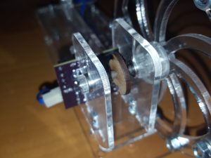 Bolt in the rear axel support to the base with a 10mm m3 nut and bolt.
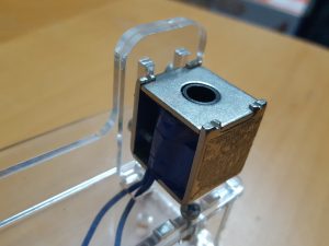 Screw in the Solenoid using the 2 x m3 6mm bolts into the slots
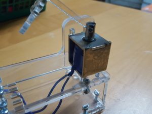 Bolt the 50mm push rod to the solenoid with an m2 x16mm bolt and a nylock nut
Apologies, for some reason the Instructions below this point have become corrupt. I’m currently working on replacing them
This diagram should give you the rest of the detail you need.

As the Acrylic some times had a very slight bend in the centre column you may need to add a 2mm spacer before the 3mm star to prevent the flywheel weights from fouling the conrod.
If you have any problems, please get intouch.
