
Tools
- Small pozi-drive screwdriver
- Scissors or sharp knife
- Cutters
- Small Pliers
- Soldering Iron / Solder (Not Essential)
- Blutak or small magnet (Not Essential)
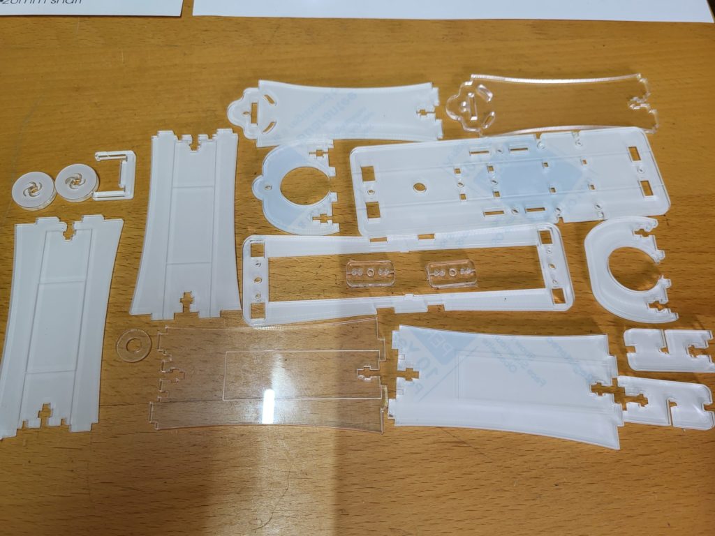
Lay out all of the pieces of acrylic, and remove the protective backing paper.
Ensure that all of the pieces have clean edges and have no burrs from the cutting process. Sand any burrs with a small peice of sandpaper or emery cloth.
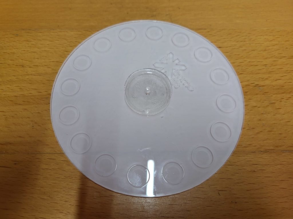
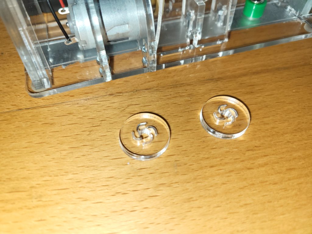
Remove the protective plastic from both of the disks and lay them flat with the bosses uppermost.
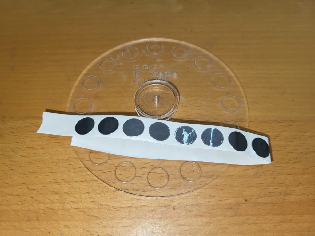
Using the strip of 12mm Foil disks

Stick them in the positions engraved on both disks.

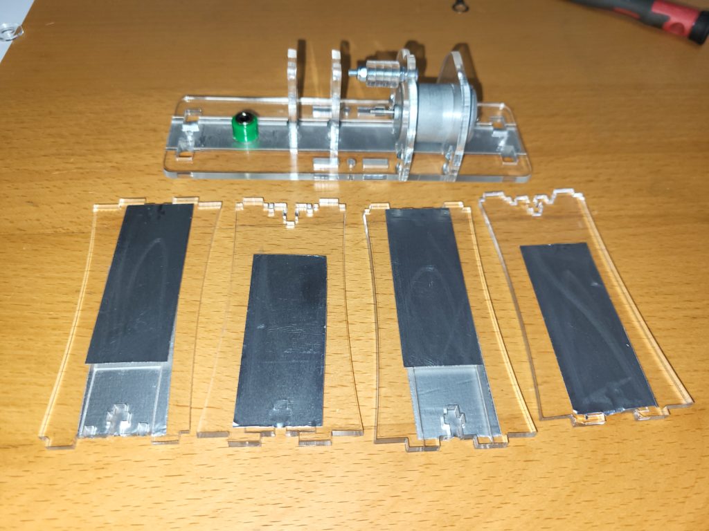
Take the 20 mm wide foil and the capacitor ends with the double engraving.

Cut the foil into strips of foil 65mm long.
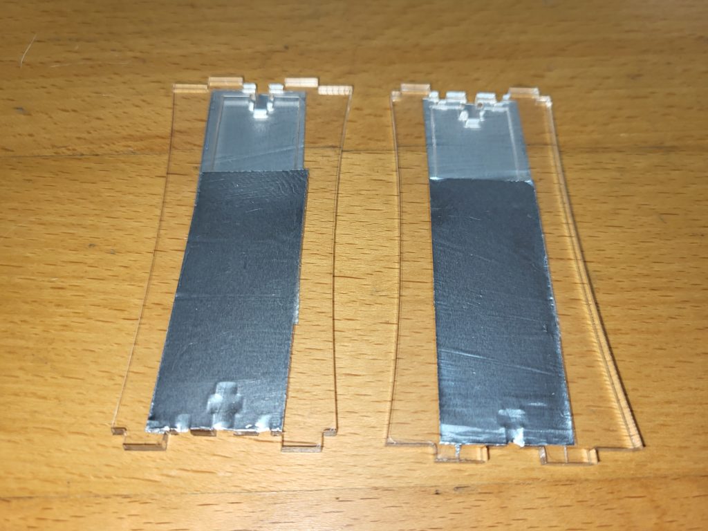
and remove the adhesive backing and stick the strips of foil onto each side of the ends acrylic using the engraving as a guide. Each end should have a piece of foil at the top on one side and at the bottom on the other.

The other two ends only have one piece of foil stuck on one side (left image) . Follow the engraving for a guide to positioning.

Cut another piece of 20mm foil and cut this 154mm long.
Stick onto the bottom of the base as shown using the engraving as a guide.

With a sharp knife cut out the foil from the 7mm hole

and place the earth post and a 2mm thick acrylic washer, into the hole from the top (the bottom has the foil)

Secure on the bottom (foil side) with the nut. Discard the solder lug.
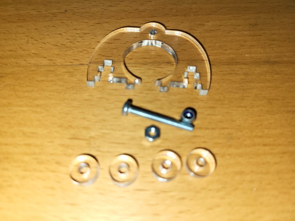
Take the front motor mount acrylic, 4 x 3mmx10mm acrylic washers, a 3mm nut an m3 nylock nut and a 25mm m3 bolt.

Attach the 25mm bolt with the nut as shown, tighten this to retain the bolt so it won’t turn in the hole.

The washers must be able to easily turn, but be tight enough not to wobble.
Place the 4 x 3mm x 10mm acrylic washers in a stack onto the 30mm bolt and secure with the nylock nut.

Take 4 x 10mm x m3 bolts and 4 x m3 nuts.
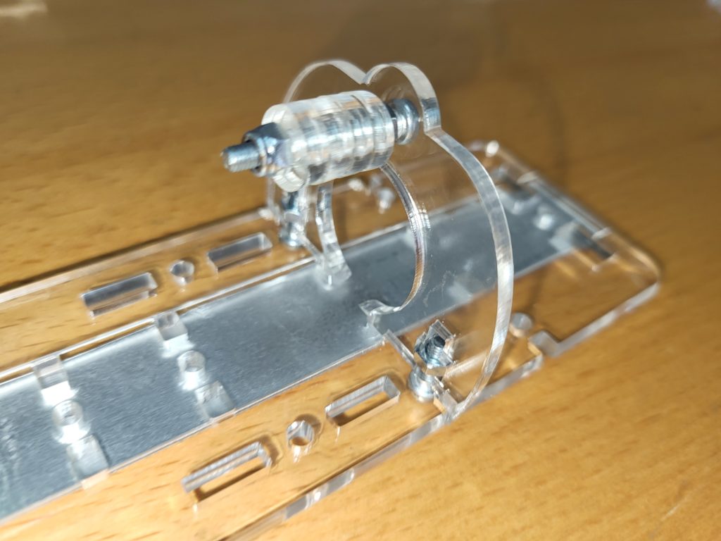
Screw the motor mount to the top (non foil side) of the base lightly with the nuts and bolts as shown.

Take 4 x 10mm x m3 bolts, 4 x m3 nuts the other motor mount and the motor.
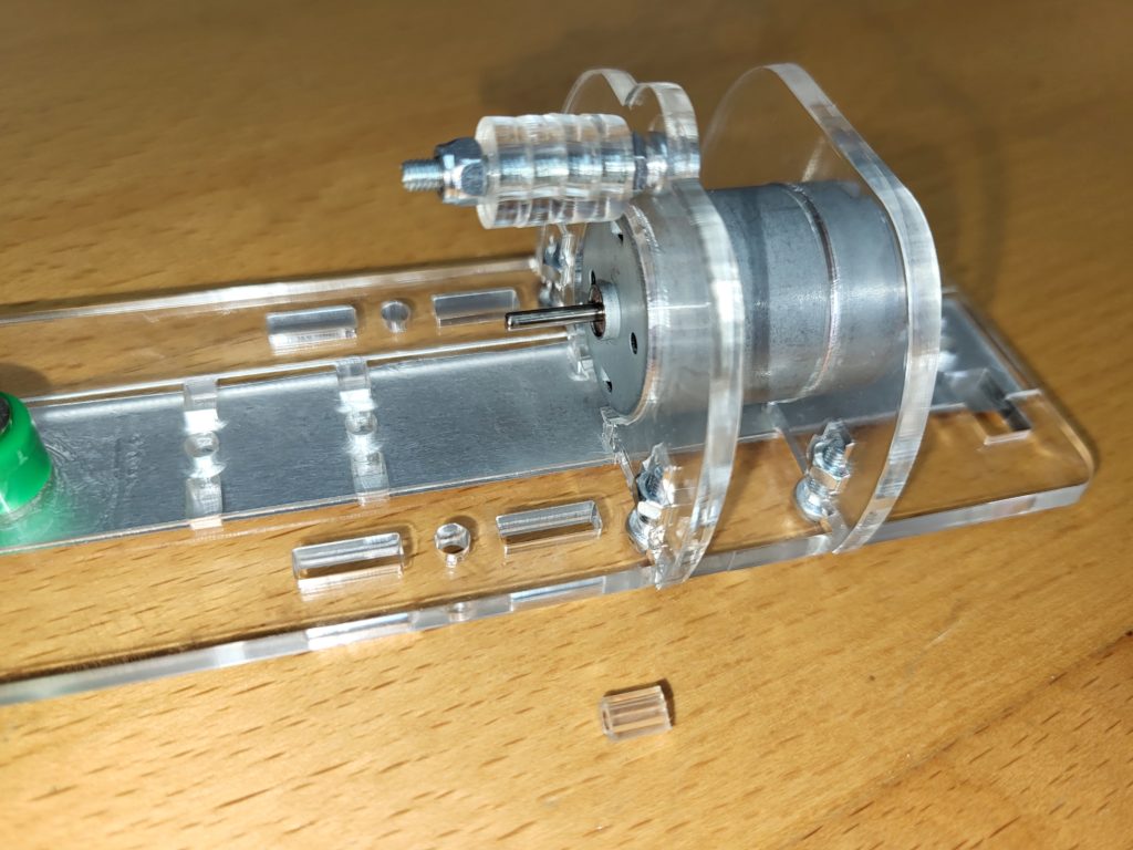
Screw the motor mount to the base with the nuts and bolts as shown.
Ensure the front face of the motor is flush with the first motor mount, and the mounts are perpendicular to the mounting plate.
Tighten all of the screws to securely retain the motor.

If your motor already has a fitted bead, skip the next step.
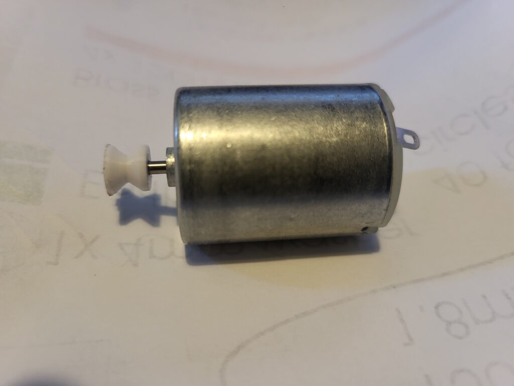
Push on the pulley on to the motor shaft ideally it should sit between 1mm and 2mm from the motor case
(Not needed if your motor already has a bead on the shaft)

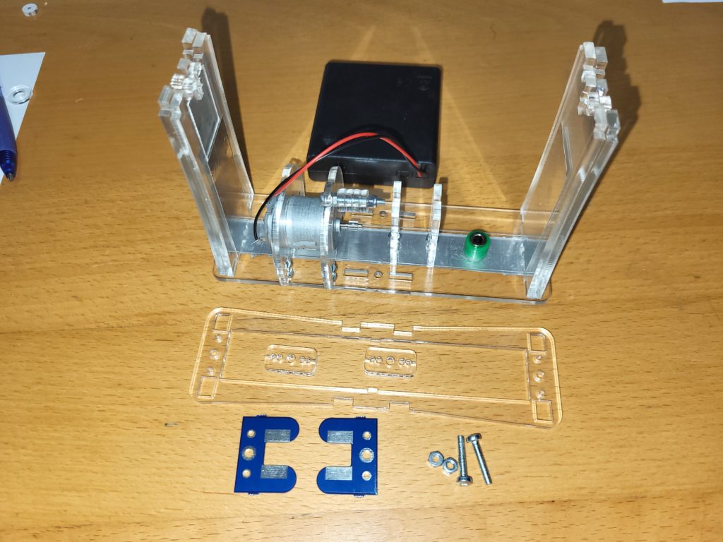
Take the three pieces of acrylic shown, 2 x m3 nuts and 2 x 10mm m3 bolts.

Screw into the base plate as shown with the m3 nuts and bolts. (Note: the design of these pieces has changed slightly from the picture to the left)
Take the end capacitor pieces.

Select a pair of end pieces, one with two foil strips and one with a single foil strip. As a guide, the top of these pieces is slightly narrower than the bottom
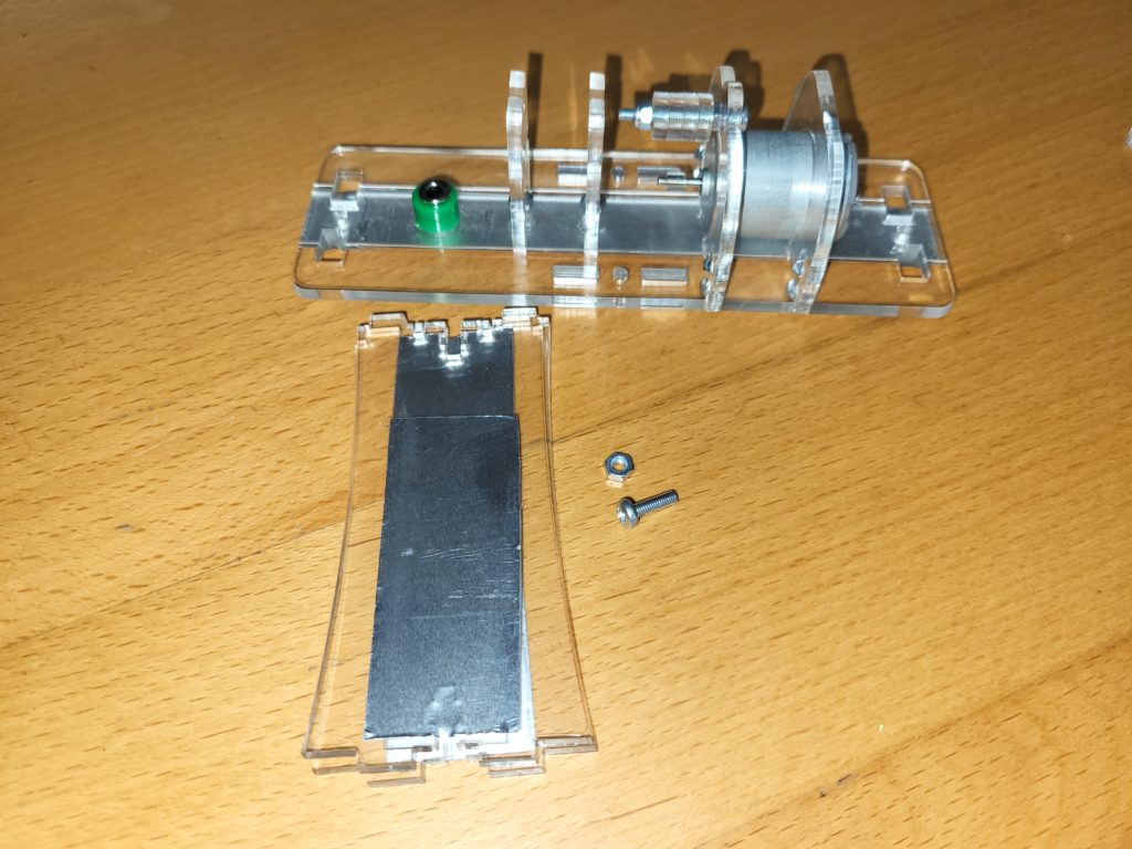
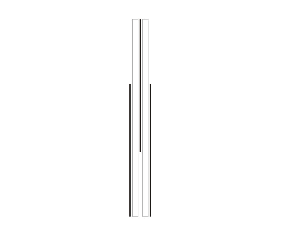
Arrange these back to back, so that at the bottom you have two pieces of foil, with the piece of foil at the top, sandwiched in the middle of two pieces of acrylic. No foil should be in contact with any of the others.

Secure the Capacitor ends with an M3 nut and 10mm M3 bolt.
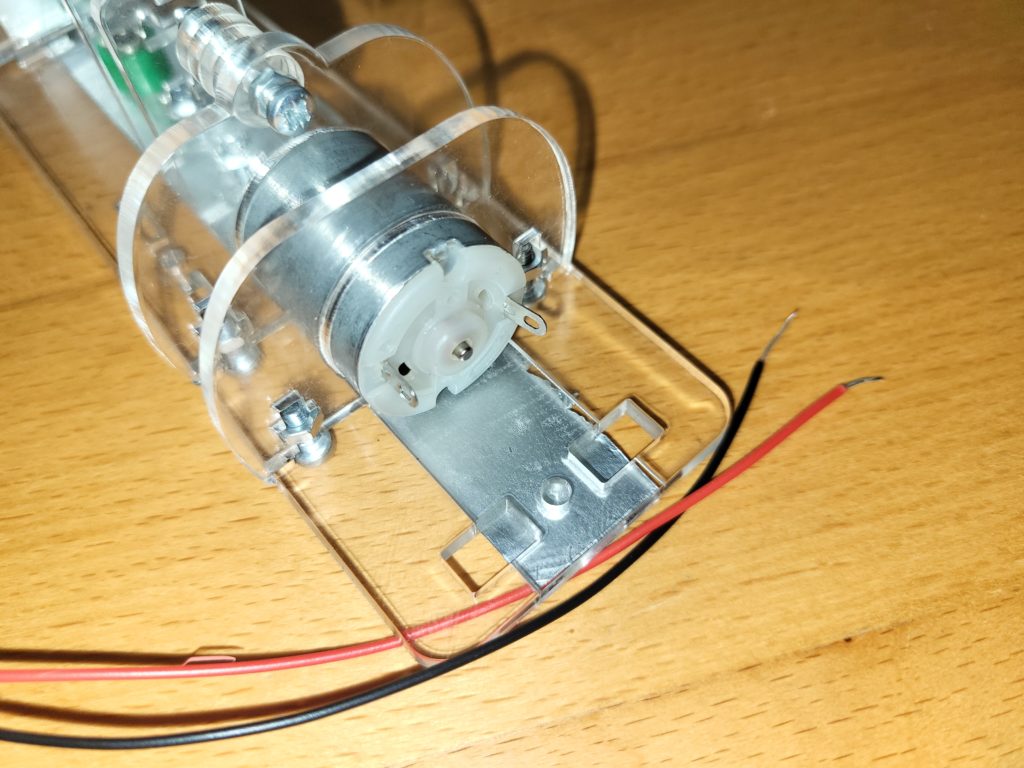
Attach the wires to the motor
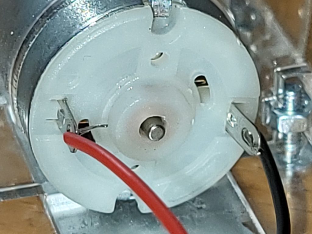
Ensure the red wire goes to the motor connector designated with the (+)
Wrap the bared wire ends around the tags and solder the motor wire in place.
Place the other pair of capacitor end plates in the same way as the first one, and secure with an M3 nut and 10mm M3 bolt.
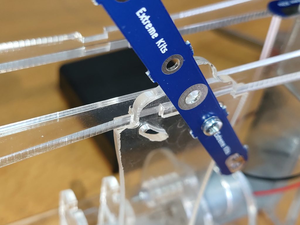
Take the gallery, two charge collector PCB’s, 2 x ball rod holders , 2x M3 nuts and two X M3 16mm Bolts.

Push in to place the gallery on to the capacitor end plates.

Place a charge collector PCB, and a ball rod holder on to the end of the gallery, and loosely attach with the M3 nut and 16mm x M3 bolt.
Repeat for the other end of the gallery.
Cut the 6mm brass foil into 4 x 25mm strips
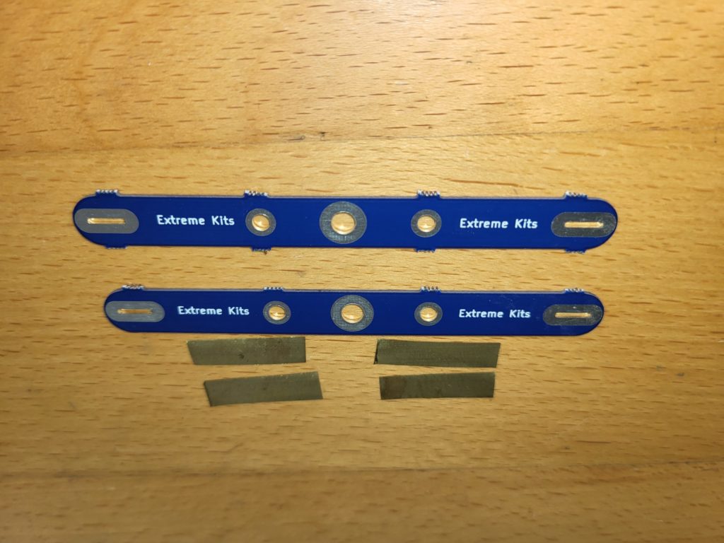
Take the two neutraliser PCBs

Fold back the brass brush 3mm from the end and solder in place.
If you don’t have access to a soldering iron, secure these with a small strip of aluminium foil tape.

with the other 3 brushes.

Take one of the completed neutraliser bars, a disk support, an m3 nut and a m3 x6mm bolt.
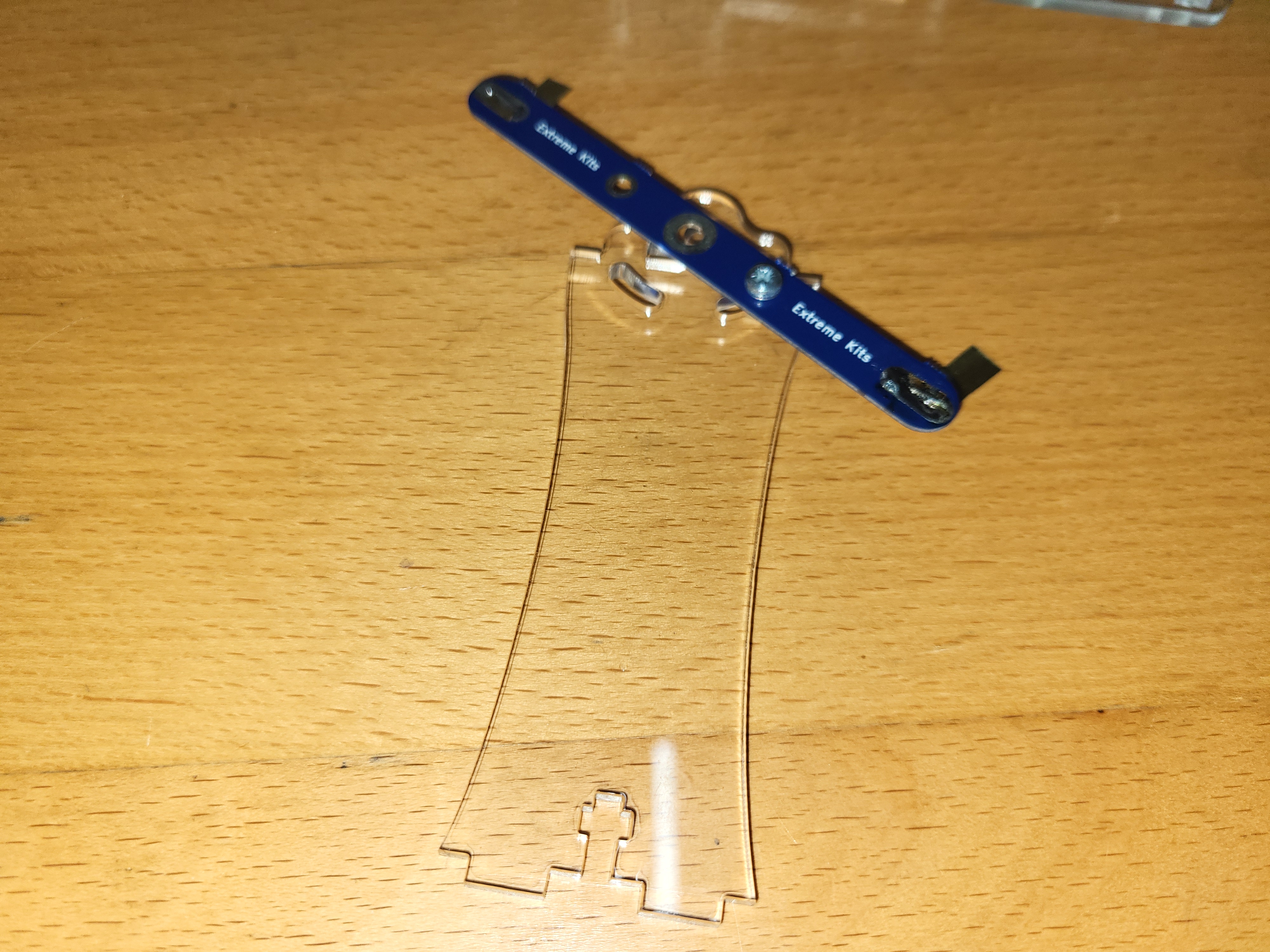
Bolt on the neutraliser bar as shown.
Do the same with the other disk support an completed neutraliser bar.

Take the completed neutraliser bar and disk support assembly, and slot into the centre of the base plate.
Make sure the disk support fits flush onto the tab on the gallery.
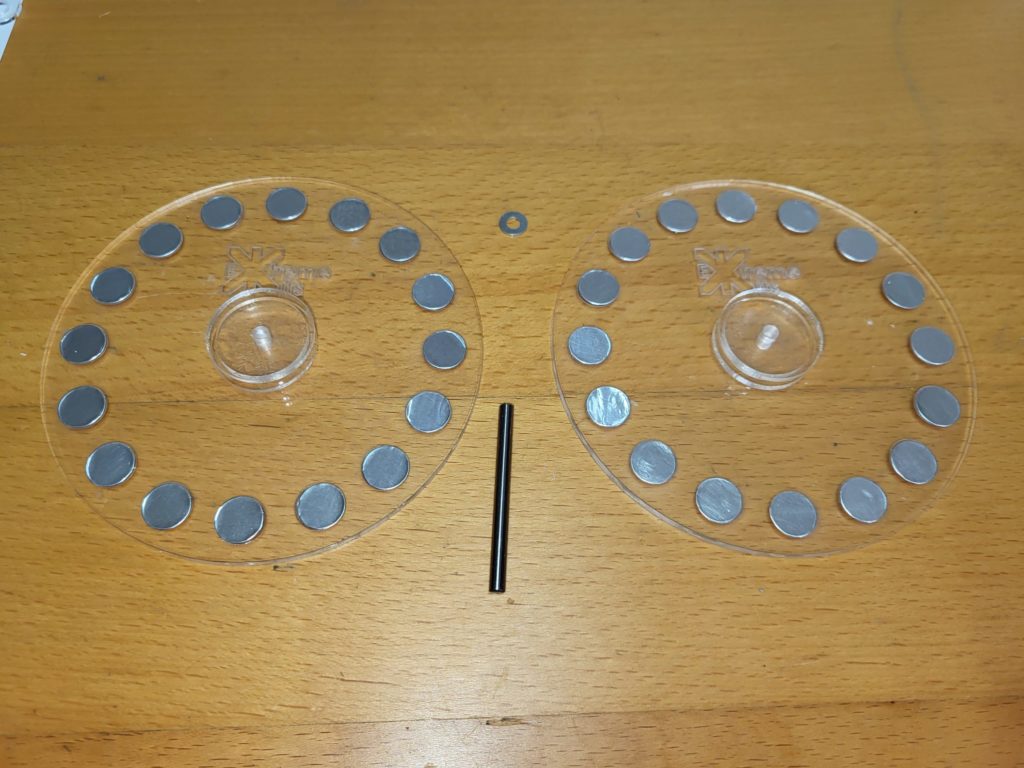
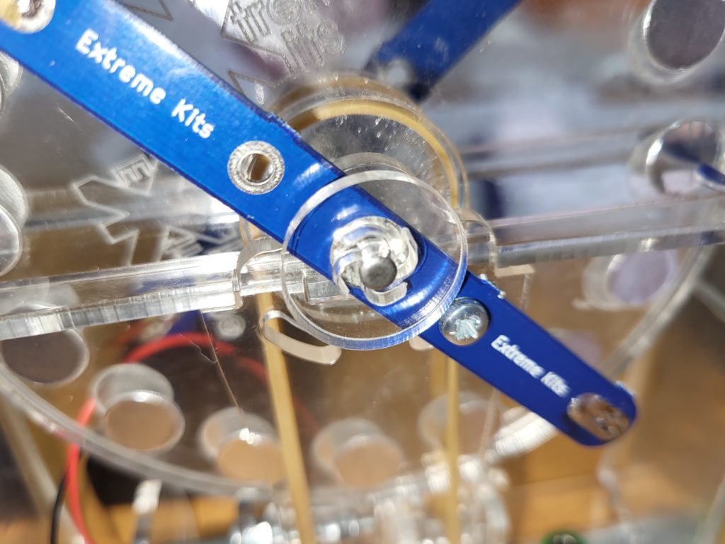
Take the two disks, an m4 washer and a 4mm x 50mm axle.

Push the axle through one disk, the washer, and through the other disk.

Push the 4mm axle with the disks into the hole in the disk support and neutraliser bar,
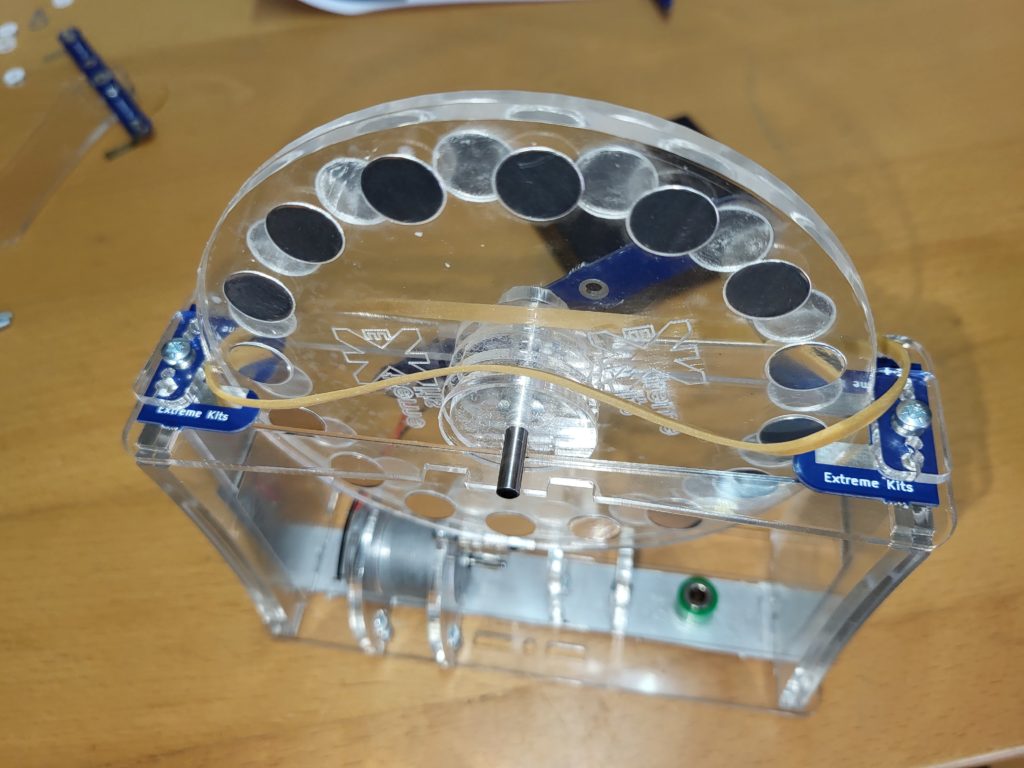
Take the 150mm elastic band and place it over both the bosses as shown.
Note: on later kits this has been replaced with a black 1.8mm rubber drive belt. The fitting method is the same.

pull the elastic band down to the edge of the disks on both sides.
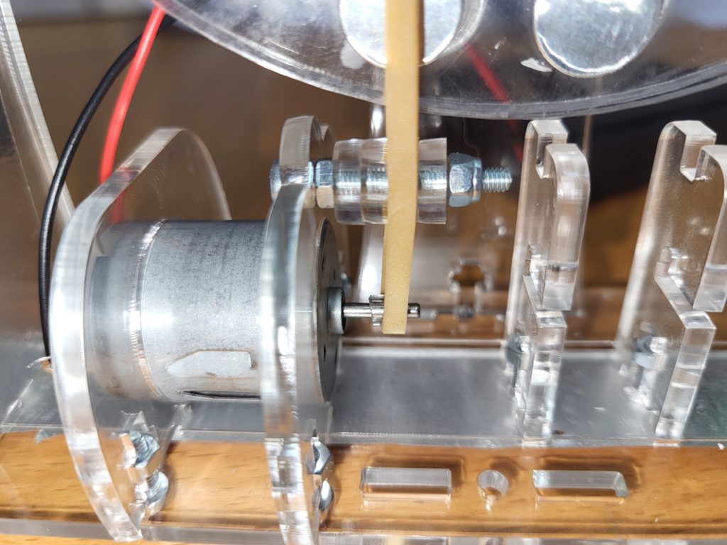
Hook one end of the elastic band over the 4 rollers and on to the motor shaft.
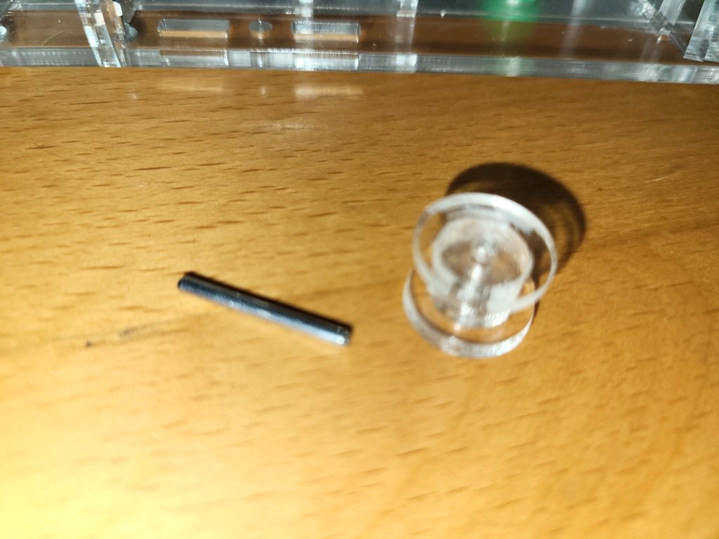
Take the 2mm x 20mm axle and the idler wheel.

hook the elastic band around the idler wheel and place between the two supports.

Secure the idler wheel and axel with the acrylic clip.

Place disks axel through the second disk support
Take the acrylic axle clips
and secure both ends of the axle with the acrylic clips.

Take the two discharge wands.
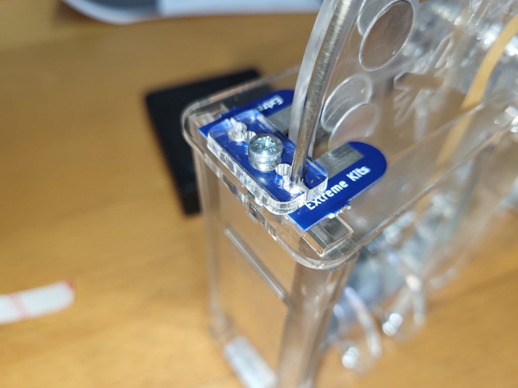
and push into the holes in the holders. The wand ends need to go through the holders, the PCB and the gallery.
Tighten up the screw and ensure the charge collector PCB isn’t fouling the disks.
Do this at both ends of the gallery.
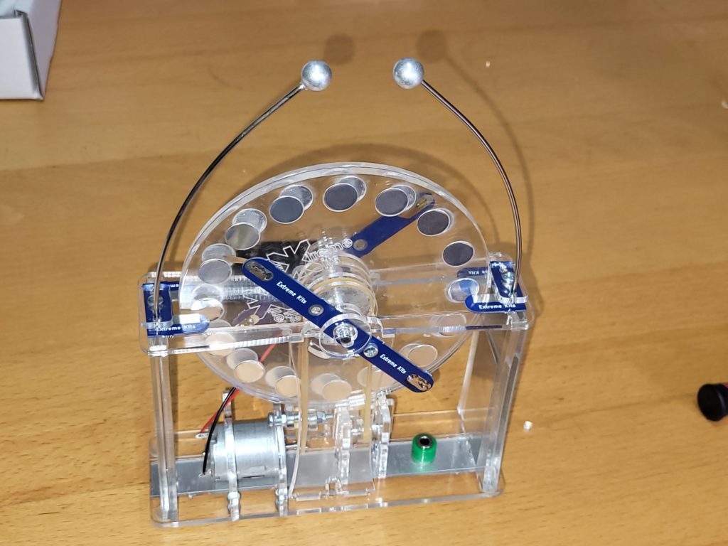
Your Mini-Wimshurst is complete.
