
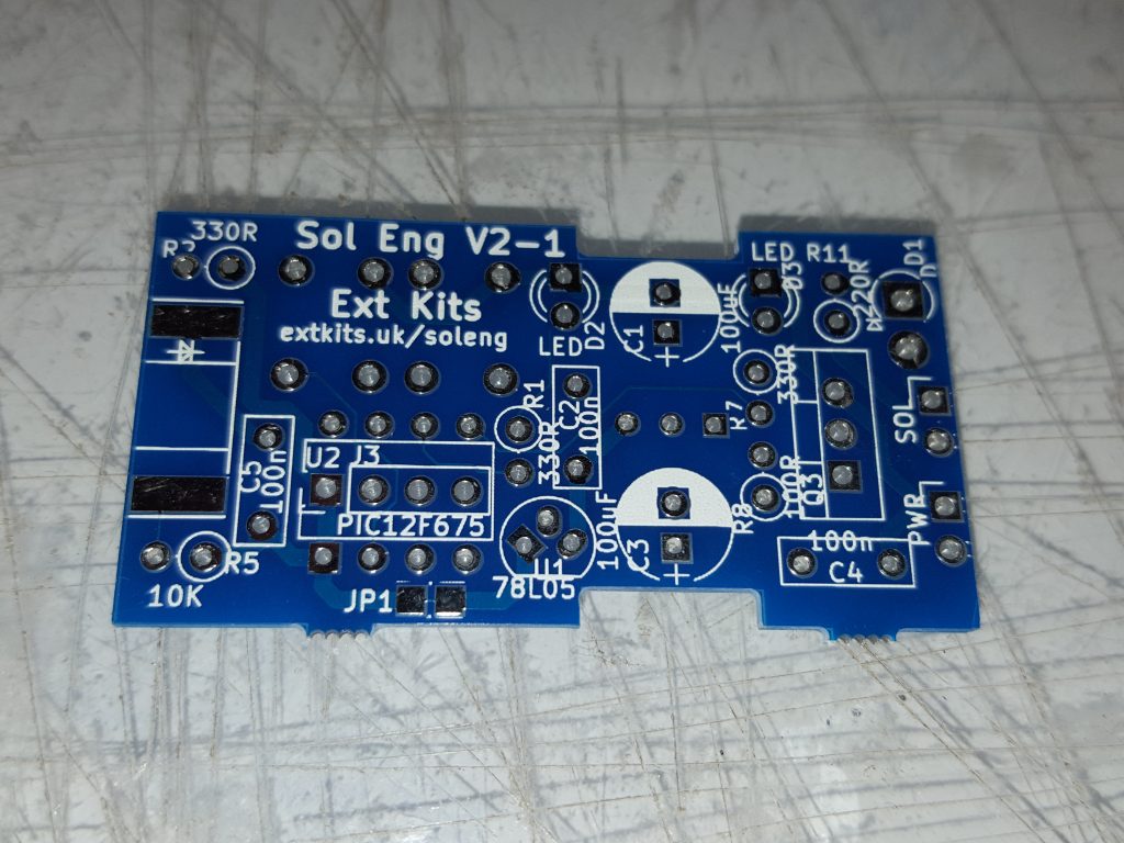
 The Solenoid Engine PCB Component side. Using an external processor means that many of the componants are not needed, please follow the positions of the components carefully below.
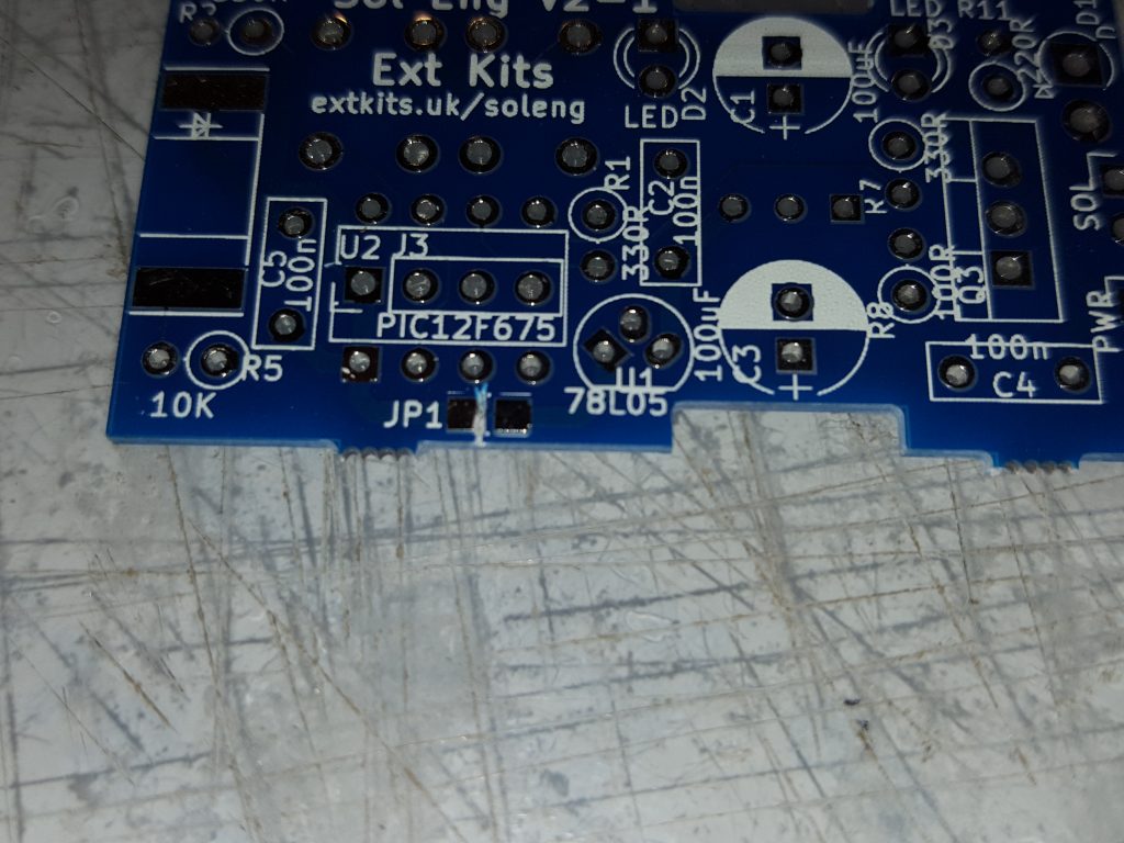 If you are using the PCB with an external processor, cut this link to ensure there is no power supplied to the external processor.
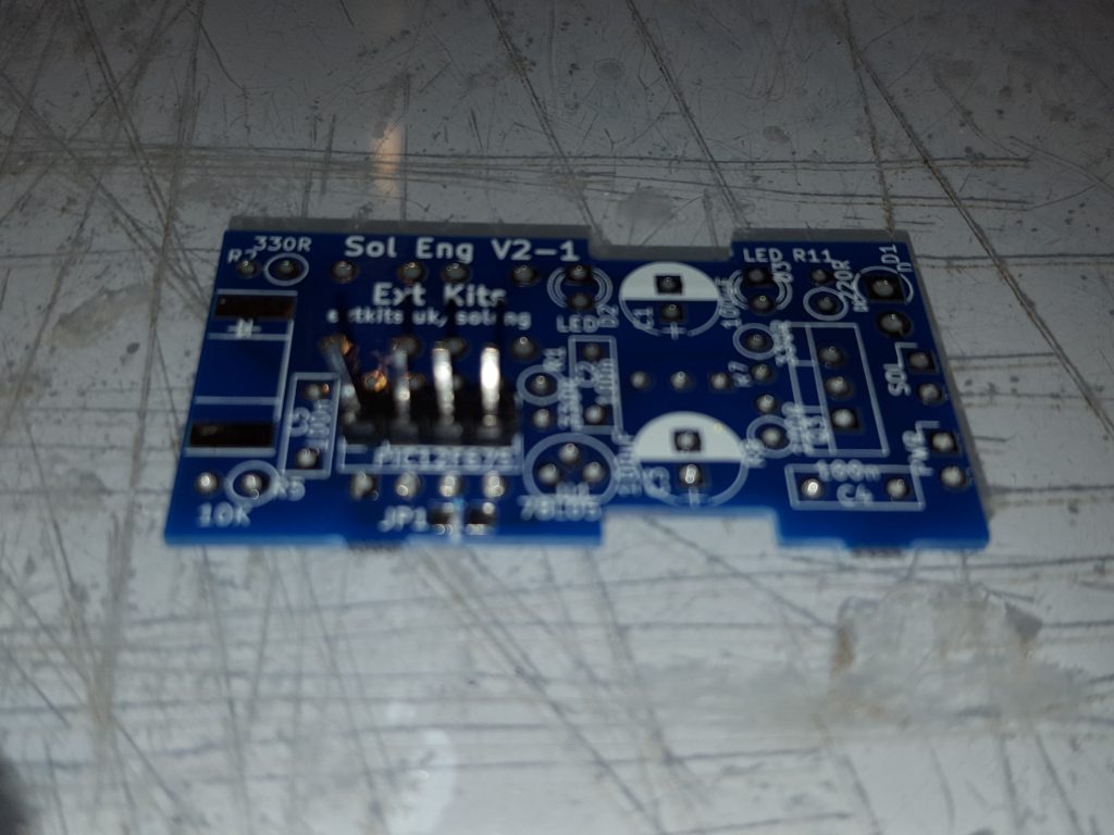 Solder in the 4 way header
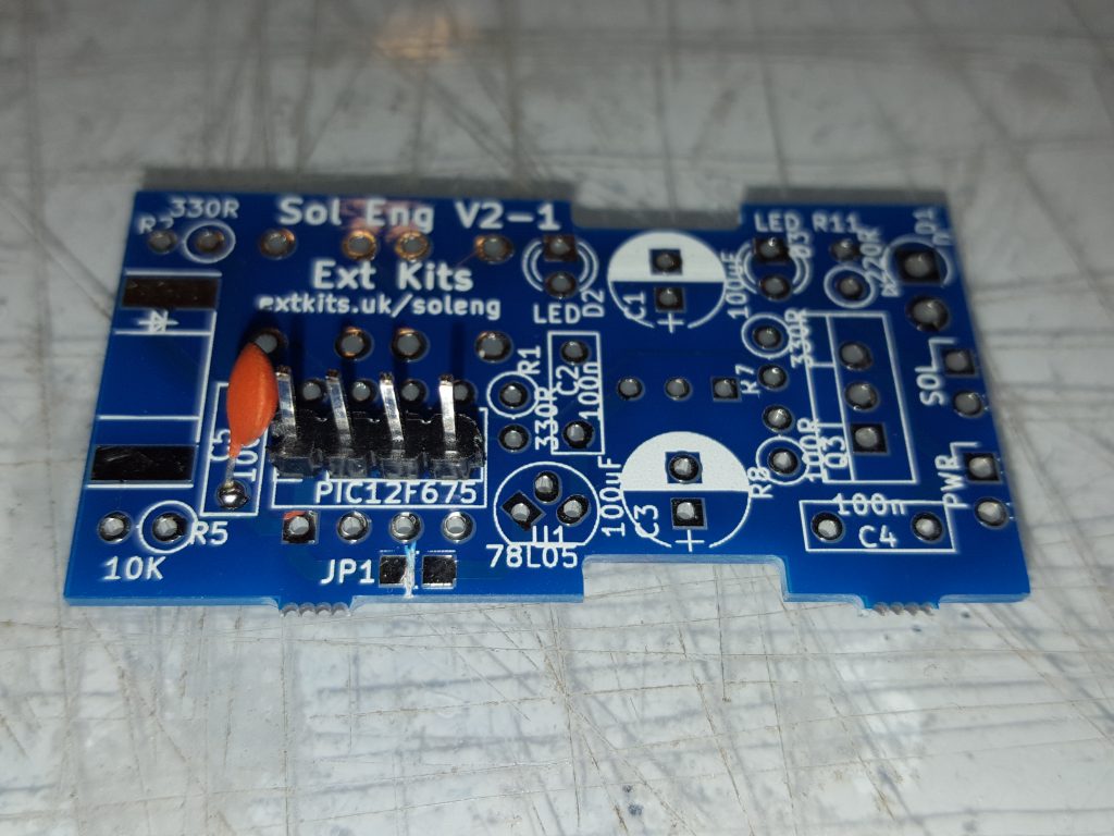 Solder in the 100nF capacitor
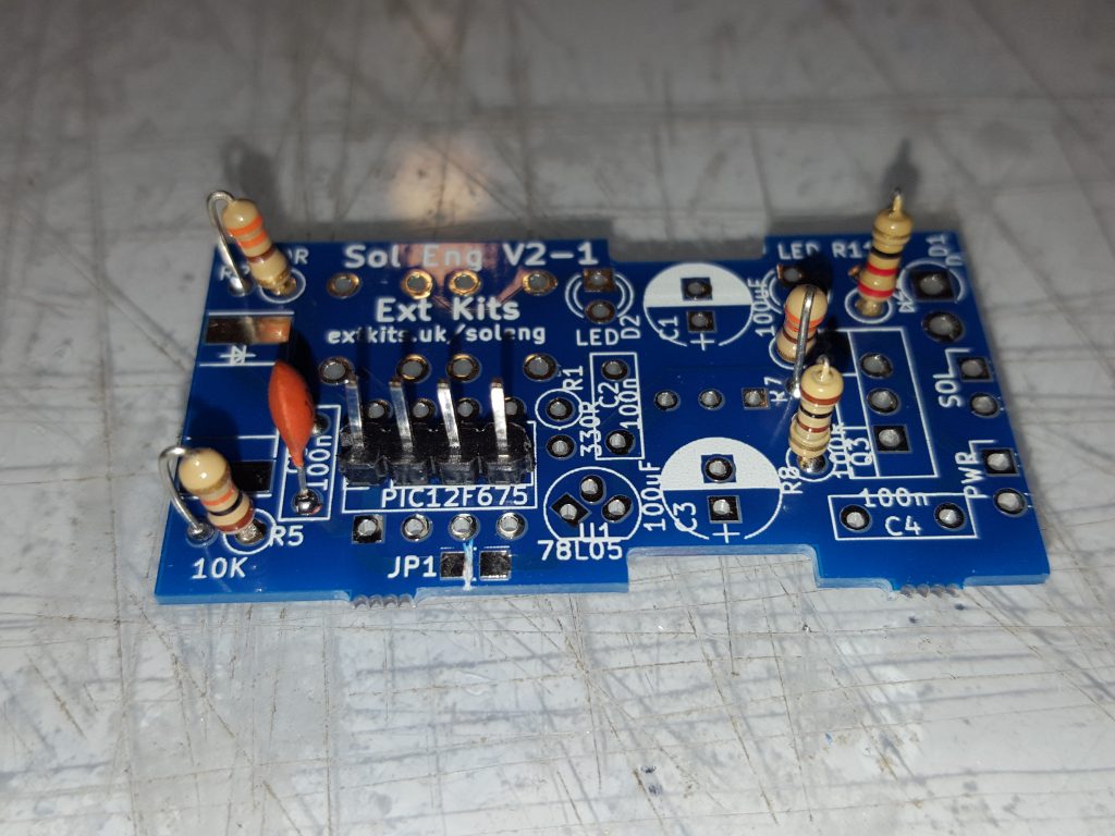 Solder in the resistors. 1 x 220 ohm (Red Red Brown), 1 x 100 ohm (Brown Black Brown), 2 x 330 ohm (Orange Orange Brown), 1 x 10K (Brown Black Orange)
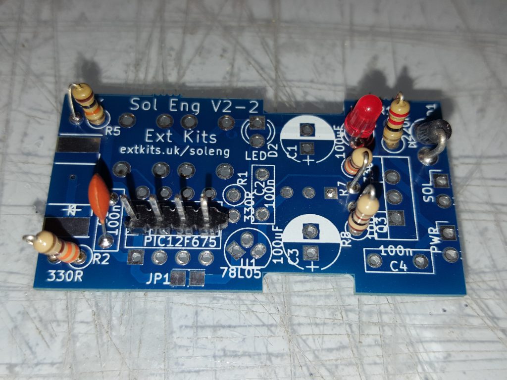 Solder in the LED shown make sure the anode (long leg) of the LED goes to the square pad on the PCB,
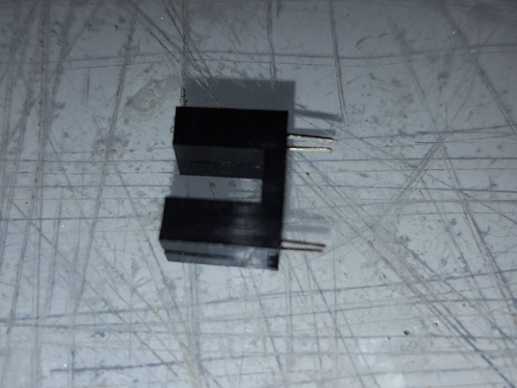 Trim the legs on the Slotted Opto to 5mm long, Slightly bend them so they nearly meet
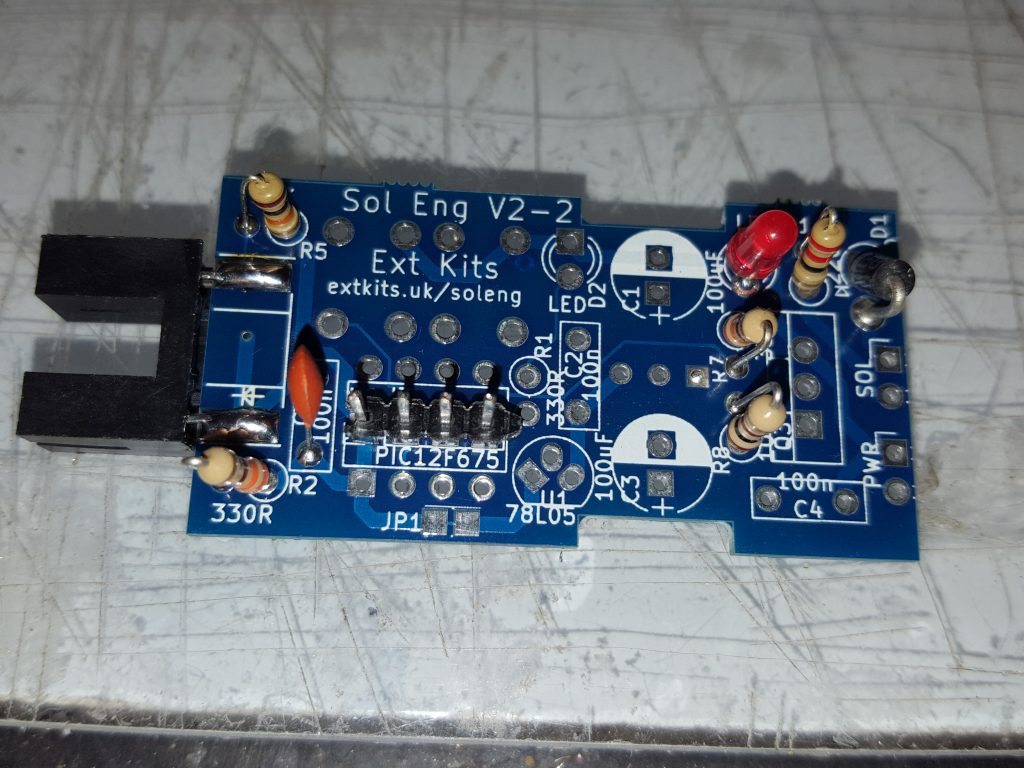 With the Diode symbol on the Slotted opto matching the one on the ident, Slide the PCB between the pins, ensure the Opto sits flush and straight to the PCB, solder the pins on both top and bottom,
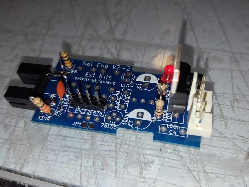 Solder in the TIP122 Transistor and the two 2 pin Connectors.
Occasionally with this kit you will get supplied with extra components. The 7805 regulator, twin electrolytic caps, 100nF cap,resistors and extra Led are not required for connection to a Micro:bit or other Microprocessor.
