
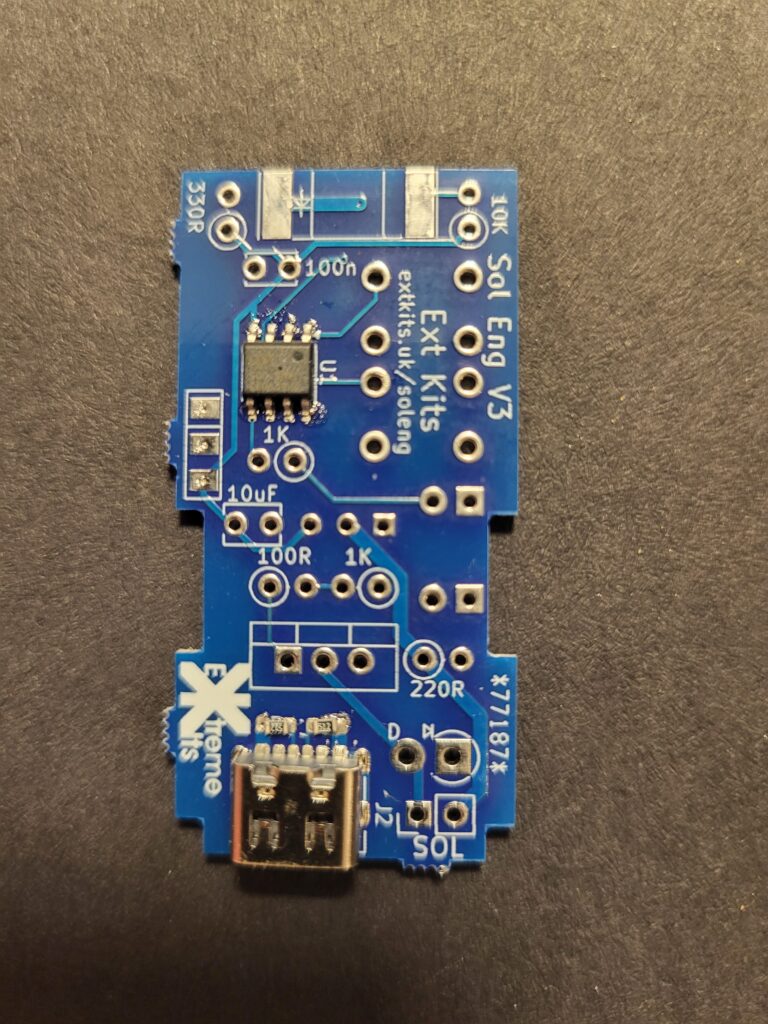
Take the PCB, and ensure its is clean and dry
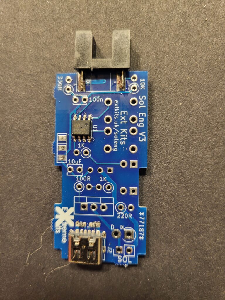
Crop the leads of the Slotted opto to 5mm and solder onto the edge of the PCB, aligning the diode symbol on the opto with the diode symbol on the PCB
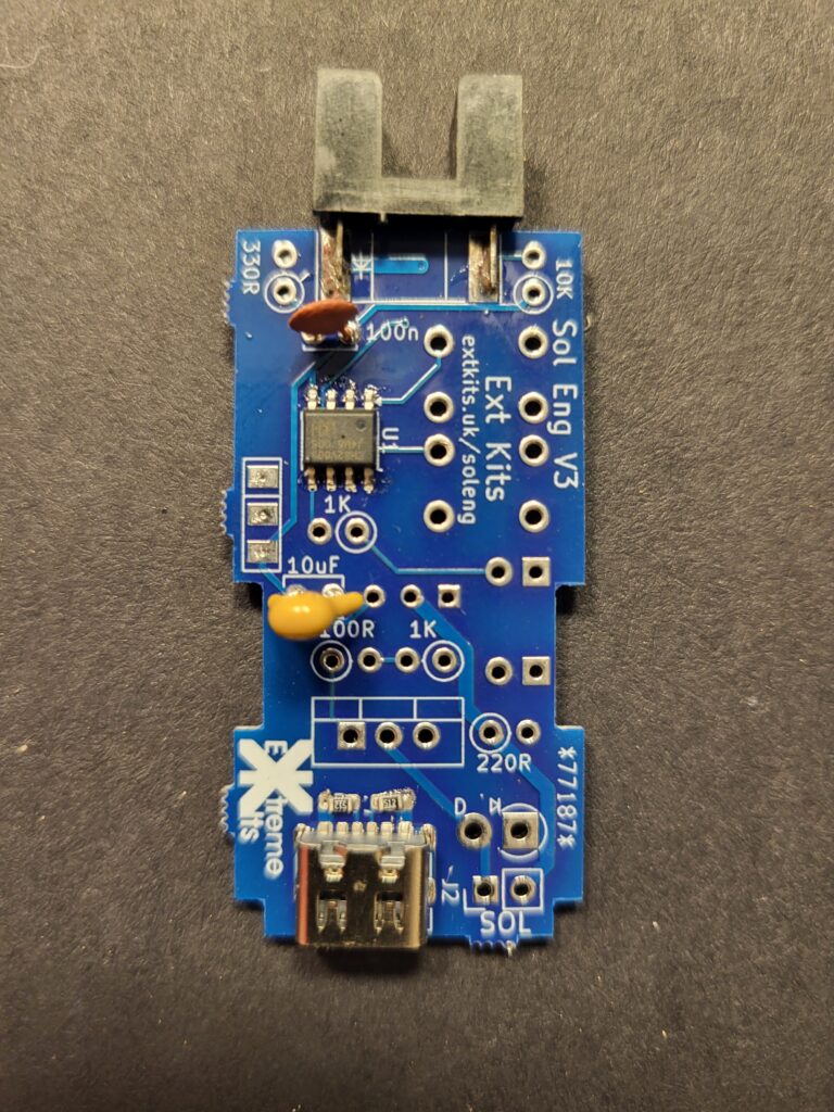
Take the 100n Capacitor (marked 104) and the 10uF capacitor (marked 106) and solder in to the PCB, you may have to bend the leads of the 10uF to fit.
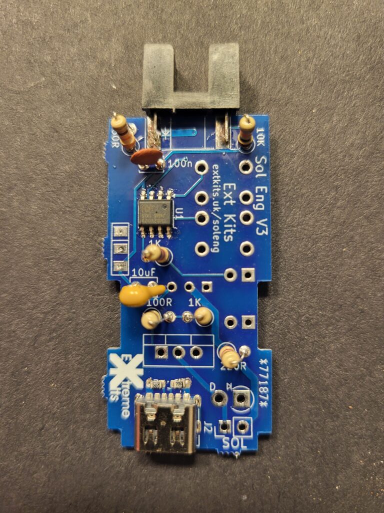
insert the resistors as shown
2 x
1k1 x
330R1 x
10k1x
100R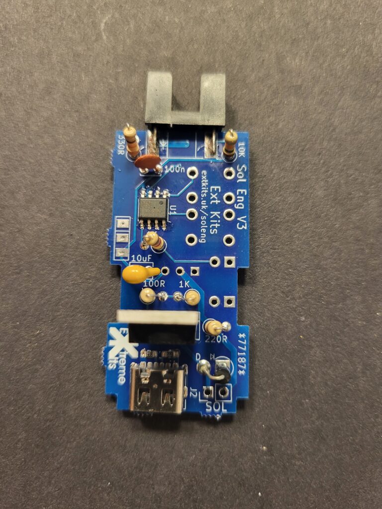
Solder in the transistor, ensuring the heat sink matches the ident on the PCB.
and solder in the diode
Ensuring that the cathode (white ring around the diode) is connected to the square PCB pad.
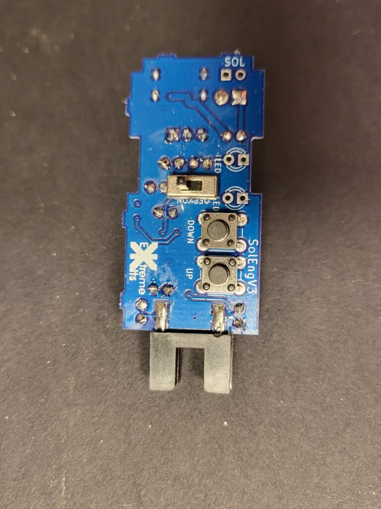
Flip the PCB over and solder in the two push buttons, and the small switch.
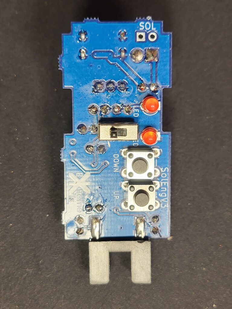
Solder in the two LED’s making sure the cathode (flat side of the LED) is soldered to the square pad on the PCB
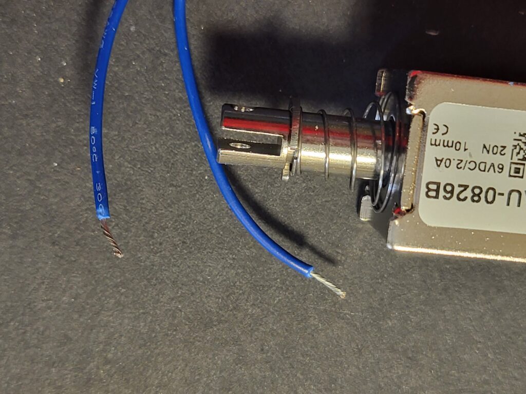
Solder the two wires from your solenoid to the PCB pads labelled “SOL”.
Pass the solenoid wires through the oval hole…
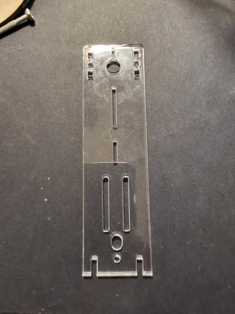
In the bottom of this piece of acrylic. (under the two parallel slots.
If the tinned wire ends won’t fit through the holes, Cut off the tinned ends, strip a short amount of the insulation, twist the wires together, poke them through the pads in the PCB and then solder.
Your Solenoid engine PCB is complete.
