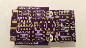
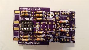
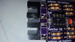
Solenoid Twin PCB component side. Remove and file down any break off tabs remaining.
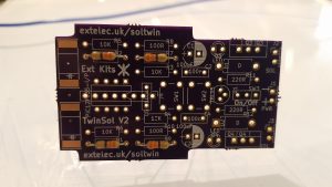
Insert and solder in the 4 x 330 ohm resistors (orange, orange Brown)
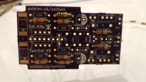
Insert the 2 x 100 ohm resistors (brown,black brown) and the 220 ohm (red,red brown) and solder in place
Insert and solder in the 4 x 10K ohm resistors (brown, black orange)
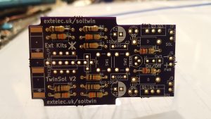
insert and solder in the 8 pin dil socket, ensure the cut out matches the ident on the PCB.
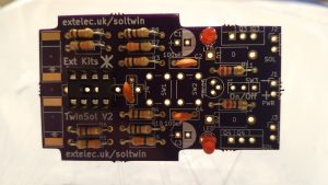
Insert and solder the two led’s and the 3 x 100nF ceramic capacitors. The LED’s flat side goes towards the square hole.
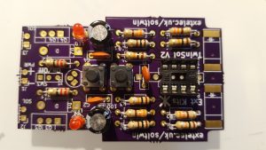
Insert and solder the two buttons and the 2 x 100uF electrolytic capacitors
Insert and solder the switch and the regulator (please note that on V2 boards the regulator ident is upsidedown.)
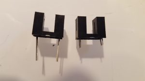
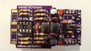
Cut off the leads on the two opto switches to 4mm
and solder onto the edge of the board, matching up the diode symbol to the PCB
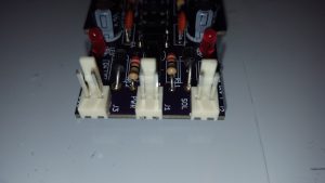
Solder in the three 2.5mm headers, ensure they are inserted the correct way around.
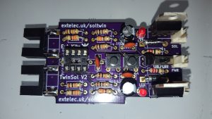
Solder in the two transistors as show,

