
Tools required
small posi-drive screwdriver, small pliers, scissors, glue
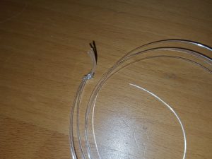 Cut 320mm lengths of the nylon and tie them together in a single knot at one end.
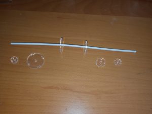 Take the middle two spacers and push them onto the spine.
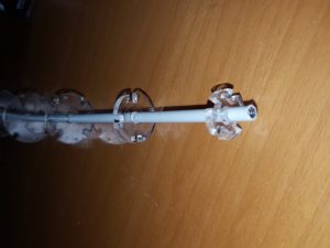 The spacers all have small holes. The bottom small spacer has big holes this needs to be at the botttom 5mm from the end under the biggest spacer. Place the rest of the spacers in size order
 Thread the nylon through the small holes in each spacer.
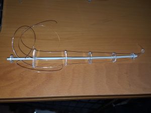 Do not thread the nylon through the bottom large holed one. Even out the spacing, and glue the spacers to the spine.
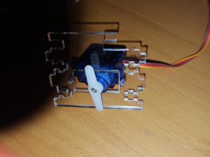 Ensure that the servo is are at its mid travel point and attach the horn that has 6 holes on either side, so it is horizontal to the body of the servo. Screw the horn into the head of the server with a small self tapping screw.
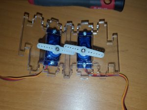 Using two m2 nuts and bolt attach the servo into an end plate as shown. Repeat the operation with the other servo ensuring that they are orientated as shown.
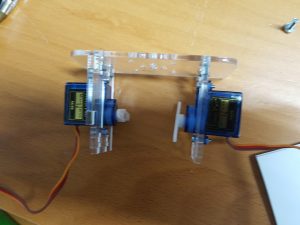 Place the two servo/end plates facing towards each other and push into the top peice
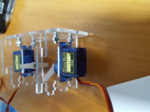 and bolt together with 4 x m3 nuts and bolts as shown.
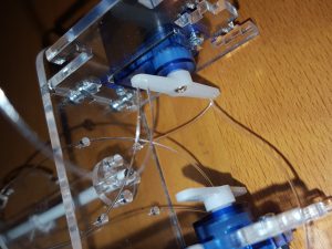 Place the spine and bottom spacer on to the top plate and secure with 4 m3 bolts. Thread the nylon through the holes in the top plate.
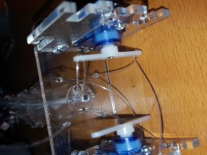 The nylon wires need to be routed to each servo diagonally. Each servo controls either left-right or Up-Down. Thread the nylon into the first hole of the horn, back to the second and back again to the third. Don’t cut off the extra at this stage.
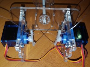 Adjust all of the nylon so that the horns are horizontal to the servos, the tenticle is straight, and there is no slack in each of the nylon wires.
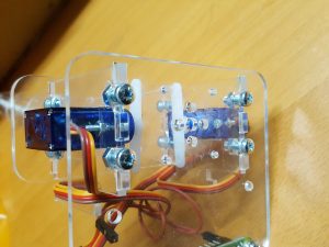 Bolt on the bottom plate with 4 x M4 nuts and bolts.
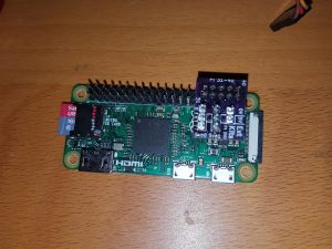 With a Raspberry pi With an attached male 40 way header, plug in the servo PCB at the 31-40 pin end of the connector.
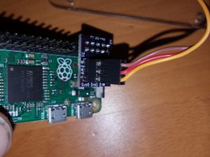 Plug in the two servos on to the three way connectors,making sure that the colours of the wires match the B,R,Y (Brown,Red,Yellow) printed onto the PCB
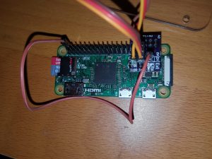 If you have a good PI power supply use the female-female connector to power the servos from your PI, Link the +5V on the servo PCB to pin2 of the 40 way header. If you are using a separate 5V power supply (recommended) use the 0 and +5V pins to supply the servos. Be careful to only have 5V on these pins and ensure they are the correct way around. Failure to do so will damage your servos and your Raspberry PI