
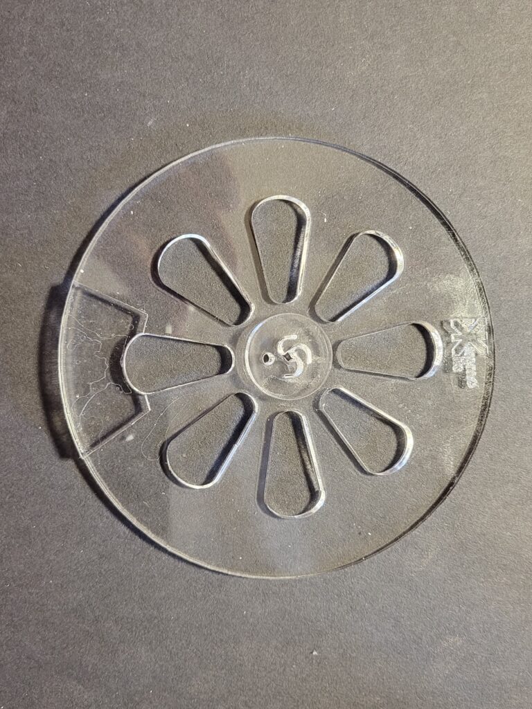
Take the flywheel
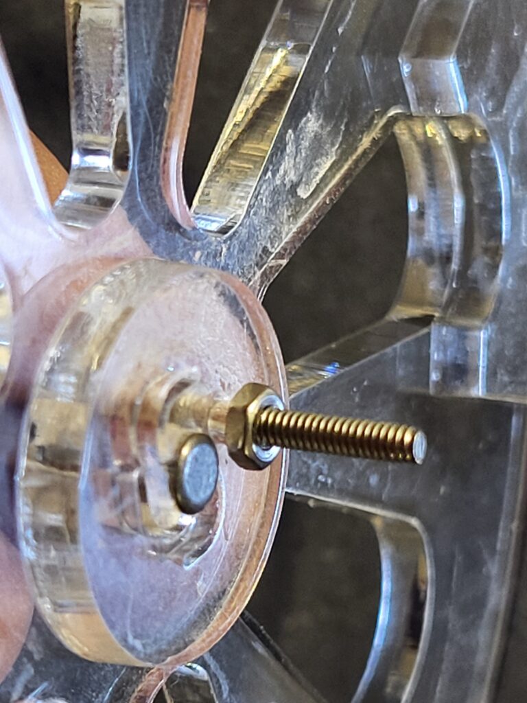
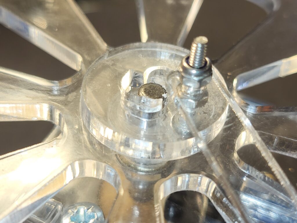
Push a 16mm M2 bolt through the small hole near the centre of the flywheel. Secure this with an M2 nut and tighten tightly.
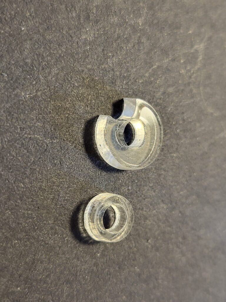
Take the 50mm x 4mm shaft. place a single 4mm bearing race and these two acrylic spacers on to the shaft
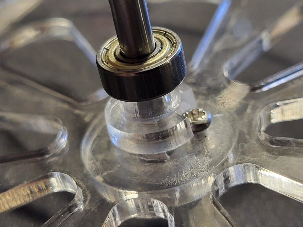
with the cut out of the spacer around the head of the m2 bolt, carefully push the shaft into the centre of the flywheel.
If the shaft is hard to push home, put the flywheel centre on to the edge of a table. With the M2 bolt over the edge, and push it home.
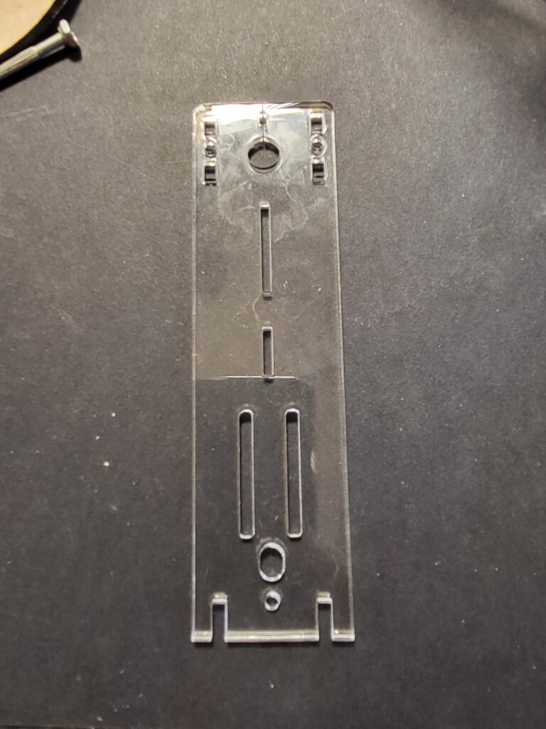
Take this side piece (with the solenoid cable threaded through)
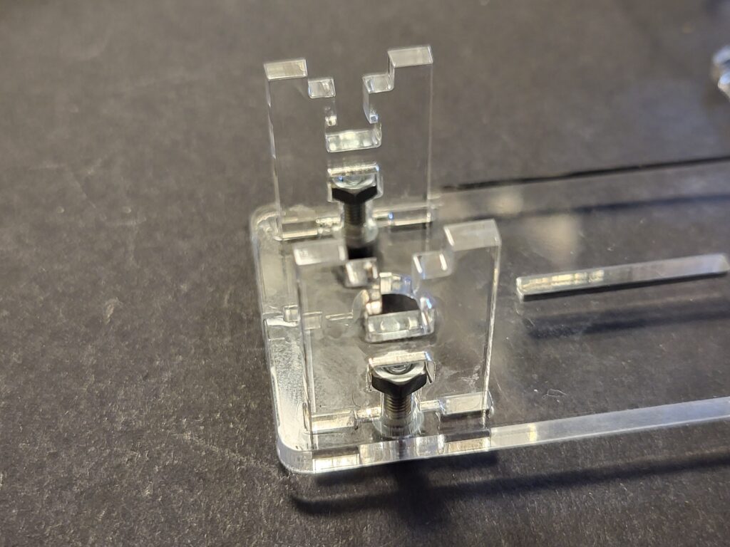
With 2x M3 x10mm bolts screw in the two spacer pieces of acrylic with 2 x M3 nuts as shown.
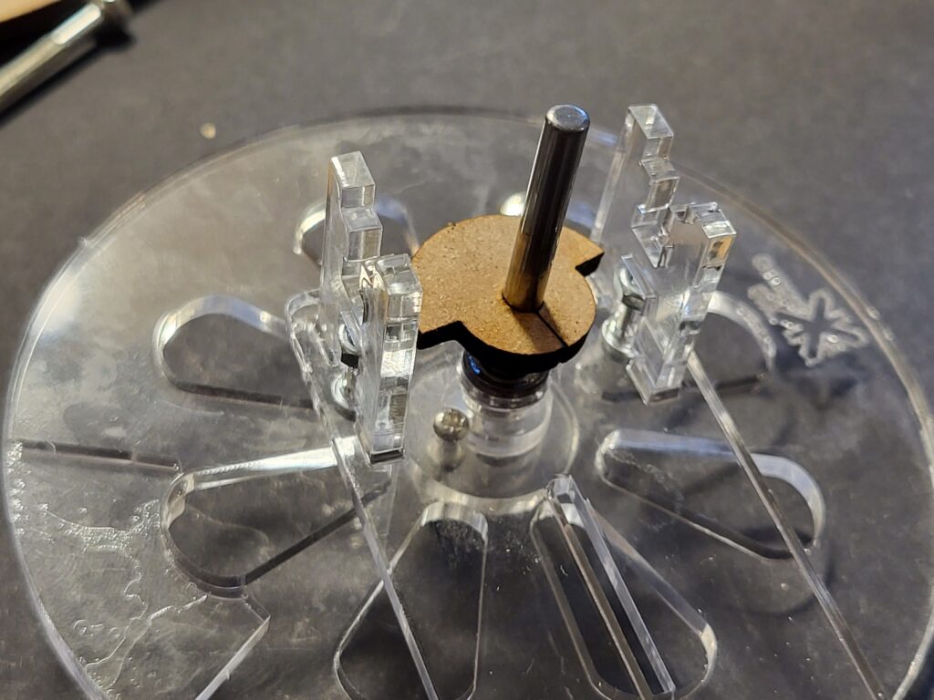
Push the acrylic over the shaft and seat the ball bearing race.
Slide the interrupter down the shaft so it is in the centre of the two spacers ( about 8mm from either side)
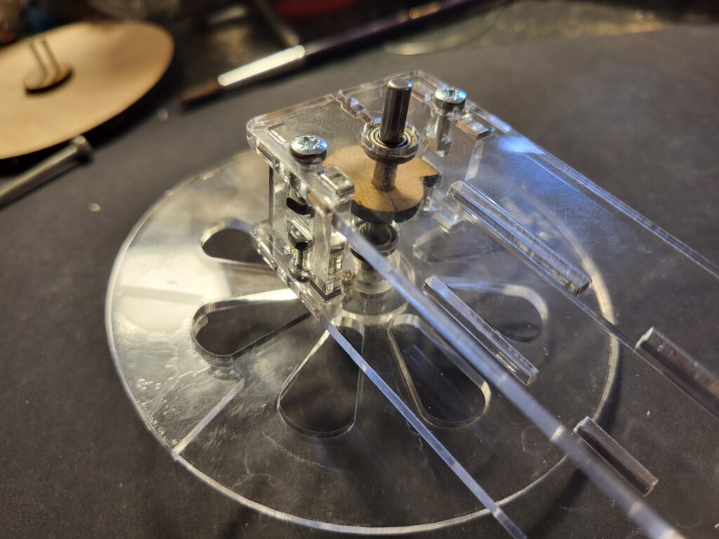
Add the other ball bearing and seat the other side piece over the ball bearing and screw together with 2x M3 10mm screws and M3 nuts.
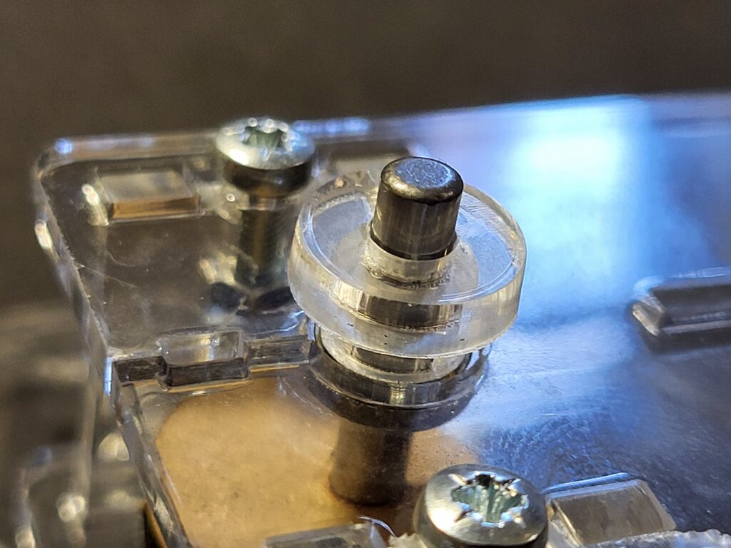
Place an acrylic washer and a split washer over the end of the shaft.
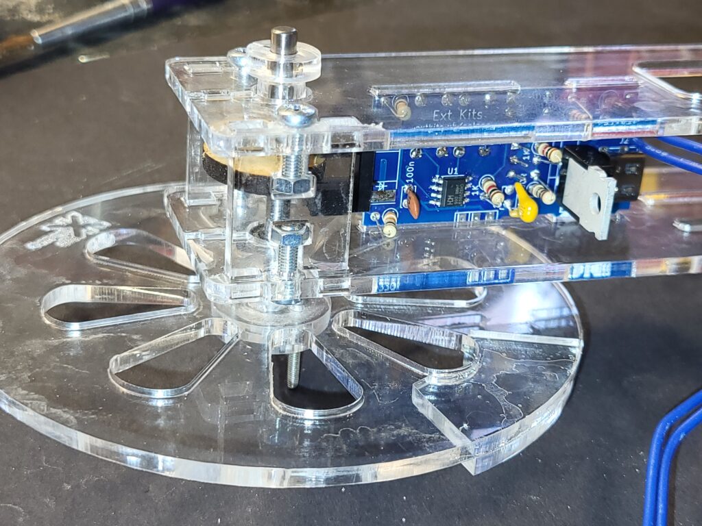
Slightly loosen the two m3 10mm bolts a couple of turns, and slide home the PCB into the slots in the side. Secure by re-tightening the bolts.
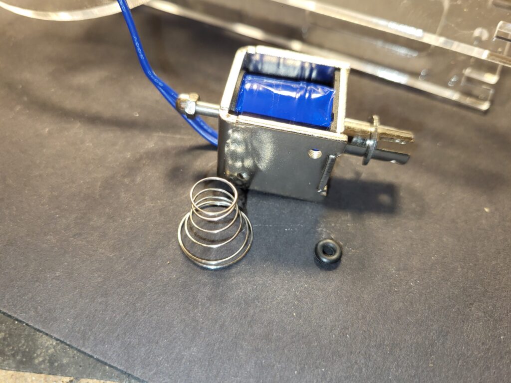
Unscrew the dome nut from the bottom of the solenoid and remove the spring and rubber ring.
With an M2 nylock nut, secure the con-rod to the flywheel.
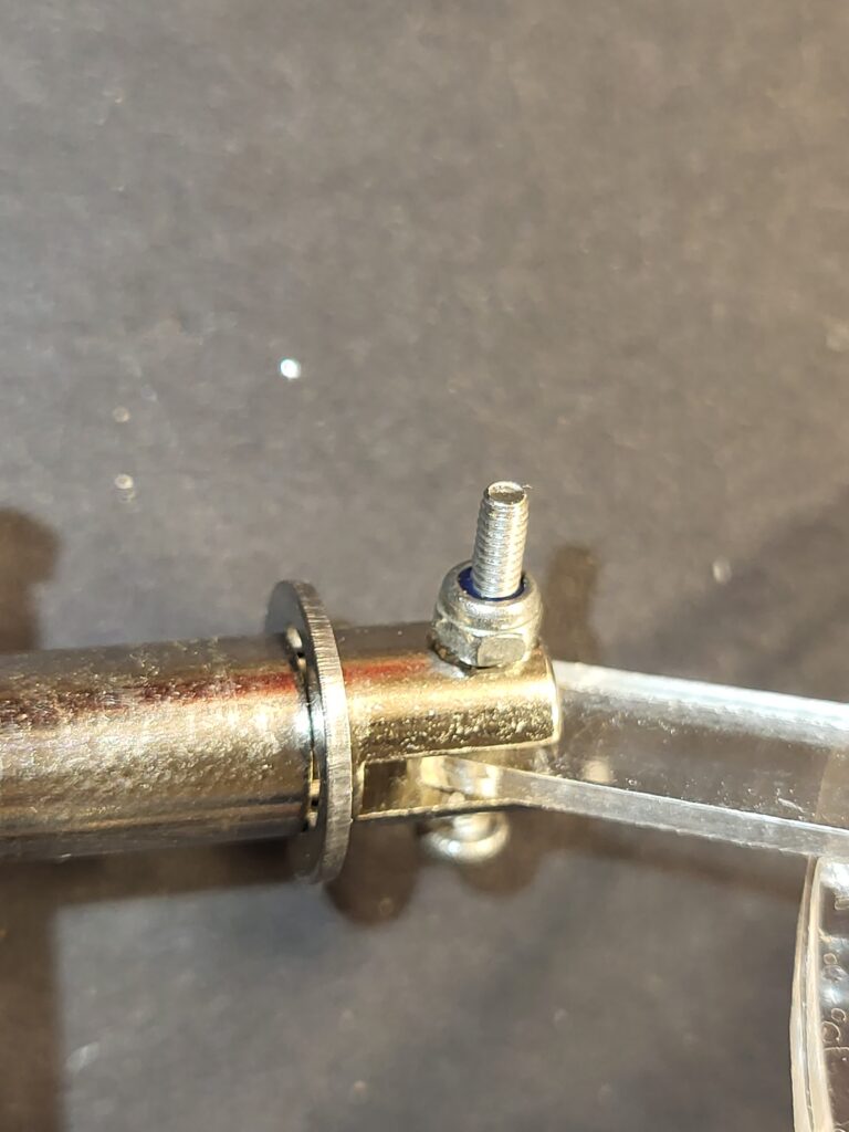
With an M2 16mm bolt and m2 nylock nut, secure the other end of the con rod to the solenoid armature.
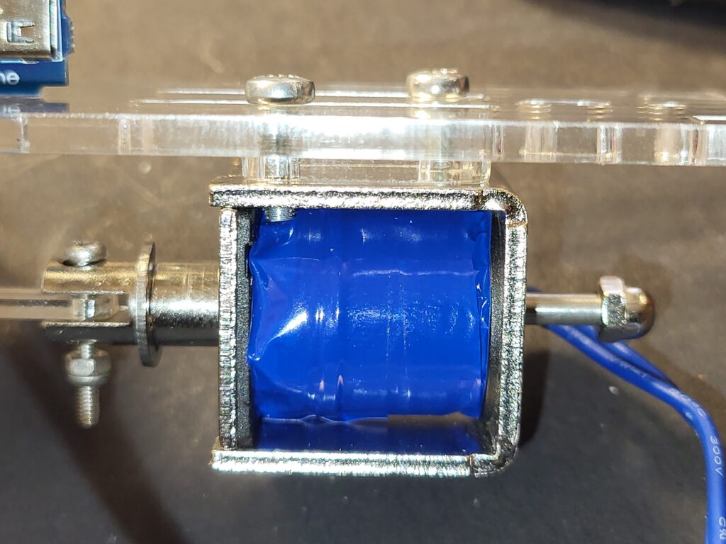
Screw the solenoid into place with 2 x M3 10mm bolts, and an acrylic square spacer plate.
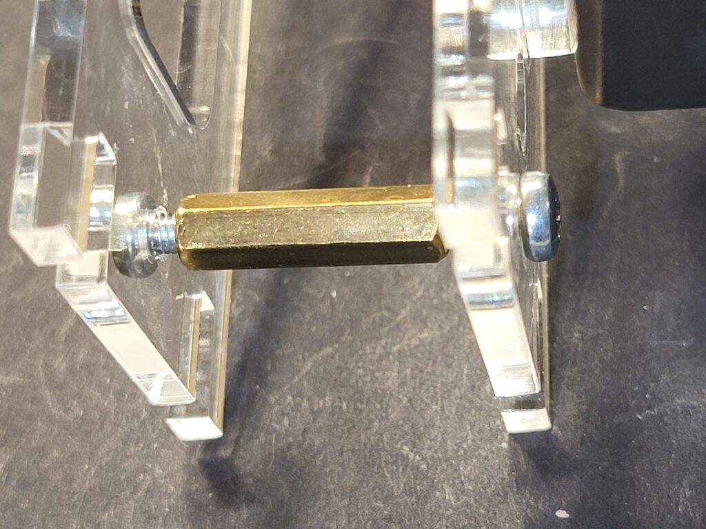
Loosly screw in the 20mm spacer and two M3 10mm bolts.
Push home the two feet into the slots, the longer end goes under the solenoid.
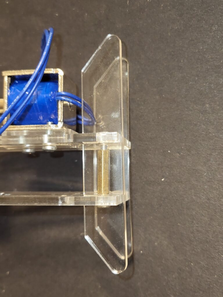
Tighten the M3 screws and spacer to grip the feet in place.
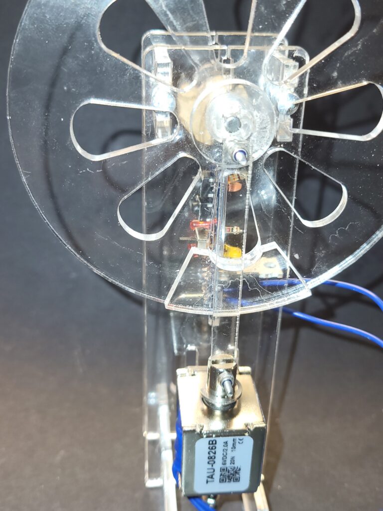
With the Con-Rod at its bottom most position. Adjust the solenoid with the 2 M3 Screws in the slots, so the armature is very slightly (1mm or so) above hitting the bottom of the solenoid.