
Content loading…
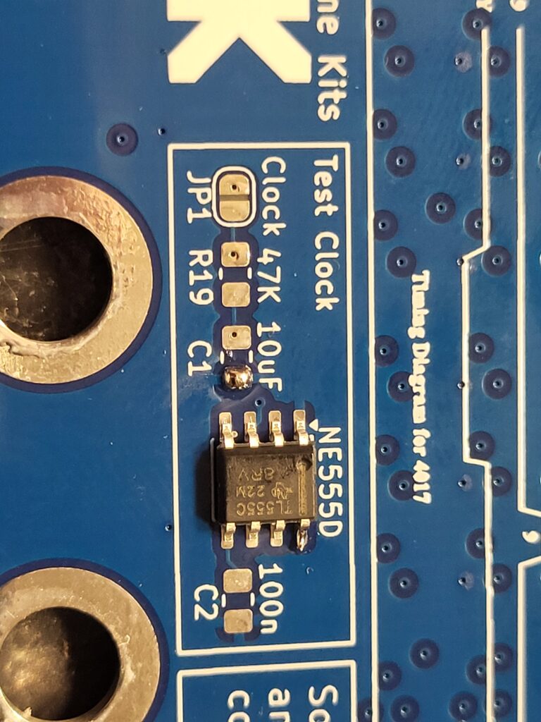
First solder in the NE555.
Ensure that the hole for pin one, is nearest the triangle ident on the PCB.
Solder one pin and get the IC in the centre of the pads, then when you are happy, touch your soldering iron and a small bit of solder to the end of each leg and let the solder run towards the IC
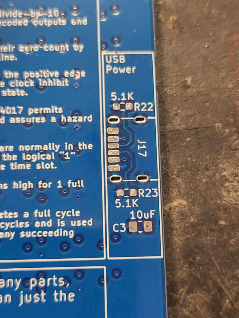
Then start with the resistors and capacitors
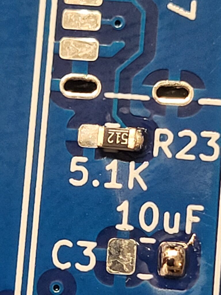
I find the easy way to solder surface mount capacitors and resistors, is to put a blob of solder on one PCB pad, and with a pair of tweezers slide the component into the molten solder.
Wait for this to solidify, then carefully solder the other end.
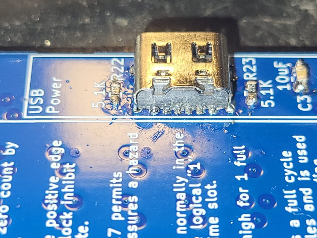
If you have solder flux coat the 6 PCB pads with a small amount of flux.
Solder in the USB C connector. Start with the case and solder this down, ensuring the 6 legs of the socket are in the centre of the PCB pads.
Then touch your soldering iron and a small bit of solder to the end of each leg and let the solder run towards the socket.
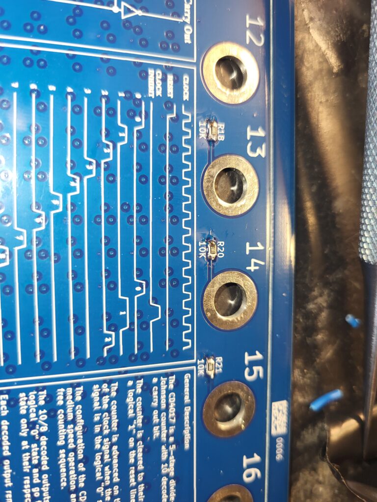
Solder in the 3 10K’s for the Reset, Clock, and Clock enable lines.
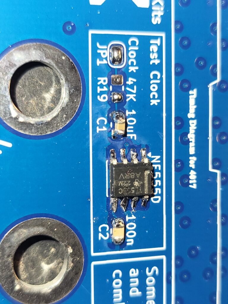
R19 dictates the speed that the NE555 will clock the 4017, 10K will give ~ 0.5hz and 47K will give ~1Hz. Values from 1K to 100K will also work.
If you want the NE555 to drive the clock, short out JP1
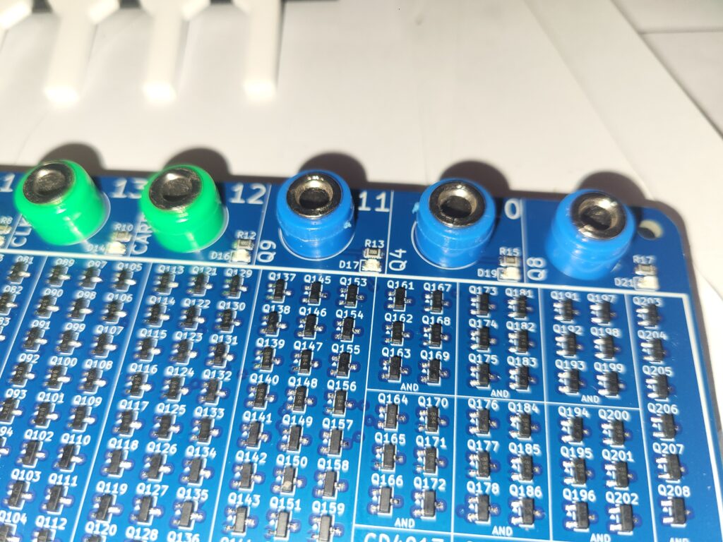
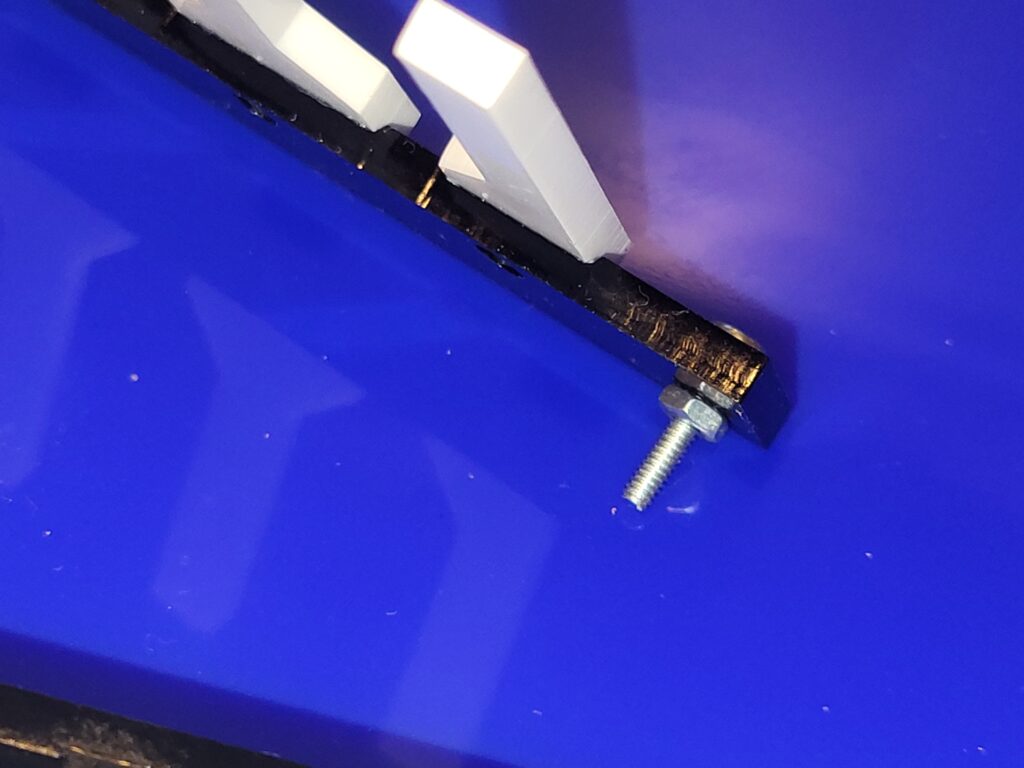
Put a m2x16mm bolt though the acrylic and secure with an m2 nut.
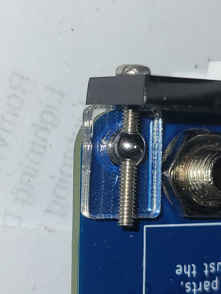
Using the 2mm clear acrylic washer, capture the thread in the m3 threaded, holed bolt.
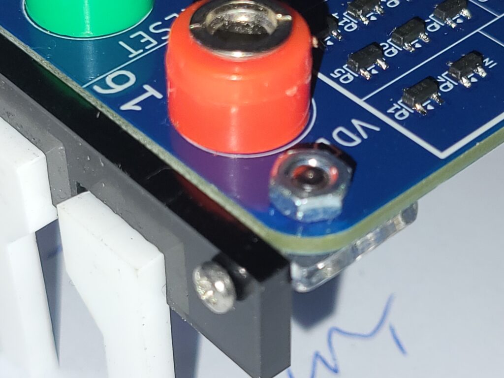
and tighten the nut to secure.
Do this for all corners.