
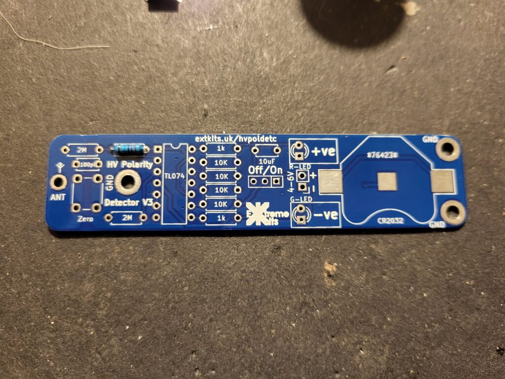
Ensure the PCB is clean and dry.
Start with the
22MAnd solder into the position shown.

Then insert the two 2M resistors
2M
Insert the 4 10K resistors
10K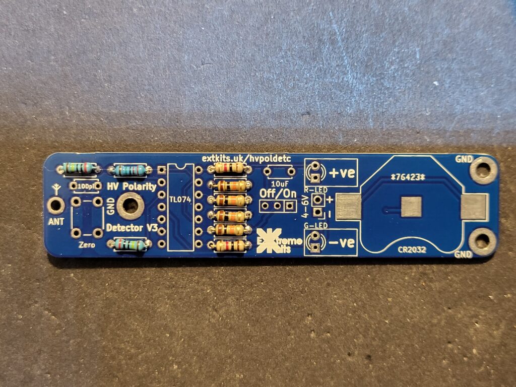
and the two 1K resistors
1K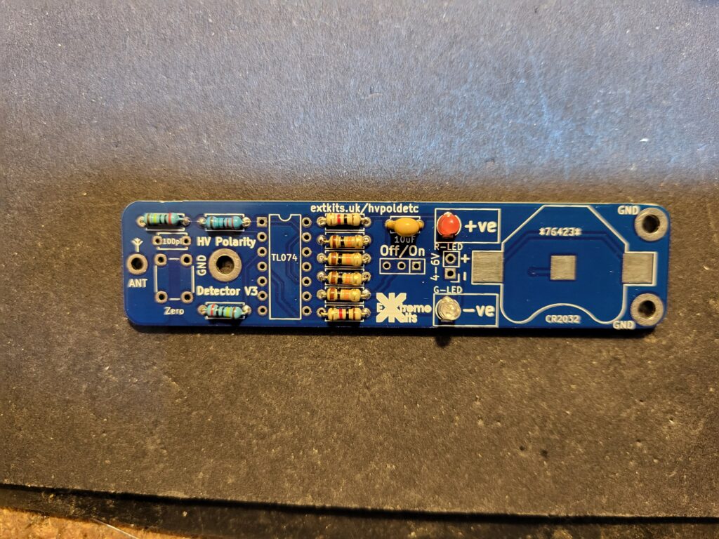
Solder in the 10uF capacitor and the two LEDs
Solder in the two LED’s Ensuring that the short lead of the LED goes to the square pad on the PCB. The LED near the +ve should be RED and the LED near the -ve should be green.
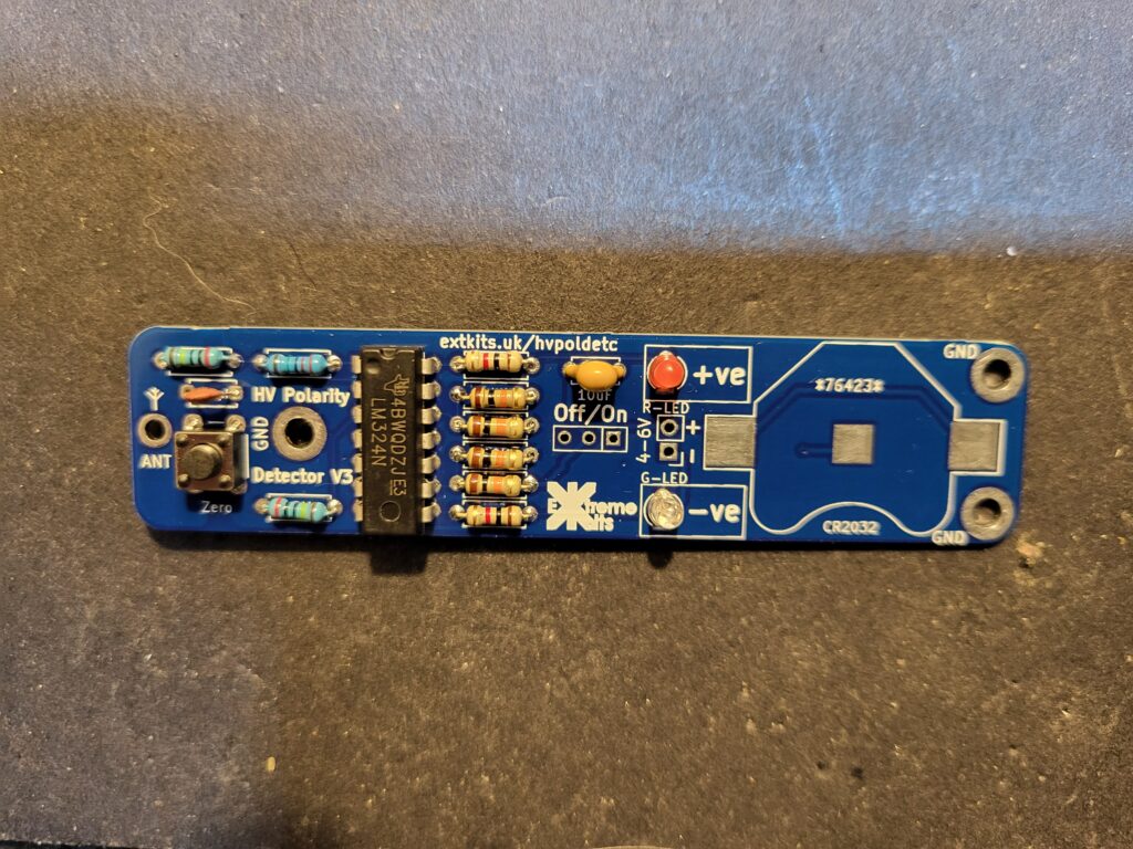
Solder in the TL074 IC ensuring that the cutout in the IC matches the cutout on the ident on the PCB.
Solder in the 10-pF capacitor, and the push button

Under where the battery connector sits tin the square in the middle
Solder in the battery connector, push the connector flush to the PCB, and solder through the holes.

Under where the battery connector sits tin the square in the middle
Repeat for the under side Battery connector.
Solder in the on/off switch (top side)
The electronics for your Polarity detector is done.